Előadást letölteni
Az előadás letöltése folymat van. Kérjük, várjon

1
Katalitikus légszennyezés csökkentési eljárások
Dr Tungler Antal egyetemi tanár MTA IKI, BME KKFT 2009

2
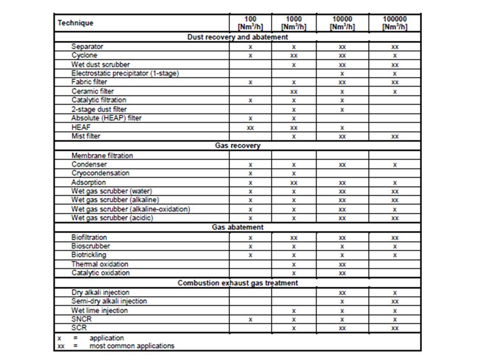
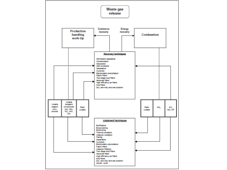
A légszennyeződés forrásai: ipari műveletek, vegyipar tüzelés, erőművek, robbanómotoros járművek. Fontosabb szennyező anyagok: CO, NO, SO2, szénhidrogének, fluorozott és klórozott szénhidrogének. Szennyező anyagok termikus és katalitikus eltávolítási módszerei: Diesel füst: oxidáció Szénhidrogének: oxidáció CO: oxidáció Mérgező szerves anyagok: oxidáció és termikus bontás 1200oC felett NOx: redukció Klórozott szénhidrogének: veszély a dioxin képződés. Ipari szagtalanítás Zsírok enyv, hal, kávé, PVC, poliuretán feldolgozás, gépkocsi fényezés.

6
Légszennyezők katalitikus oxidációja
szennyezett levegő hőcserélő katalizátorágy tisztított levegő láng tüzelőanyag

7
Légszennyezők katalitikus oxidációja

8
Katalitikus hatású gáz szűrő
Cr-V tartalmú katalizátor szálasanyagra felvive

9
Bioszűrő Biomosó

10
NOx kibocsátás salétromsavgyártásnál, ipari tüzelőberendezéseknél
Véggázok % Nox % O2 tartalmúak. Redukálószerek: H2, szénhidrogének, NH3. H2 + NO2 NO + H2O H2 + 2NO 2H2O + N2 A hidrogén redukálószer esetén a katalizátor monolit hordozós platina. A szükséges minimális belépési hőmérséklet: hidrogénnel 470K, metánnal 750K, propán-butánnal 520K. Az oxigén eltávolítás, mivel gyorsabban reagál, mint a nitrogénoxidok, növeli a redukálószer igényt és a hőmérsékletet. Az ammónia használatának az az előnye, hogy szelektíven csak a nitrogénoxidokkal reagál. Ilymódon kevesebb kell belőle, viszont drágább, mint a szénhidrogének. 6NO2 + 8NH3 7N2 + 12H2O NO + 4NH3 5N2 + 6H2O Katalizátorok: Pt, Ru/ Al2O3, Cu-zeoliton, V2O5 /Al2O3, TiO2.

11
A gépkocsi kipufogó gázok tisztítása
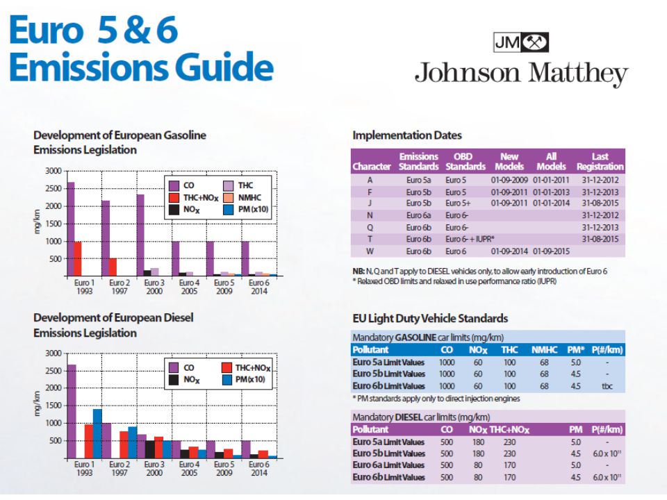
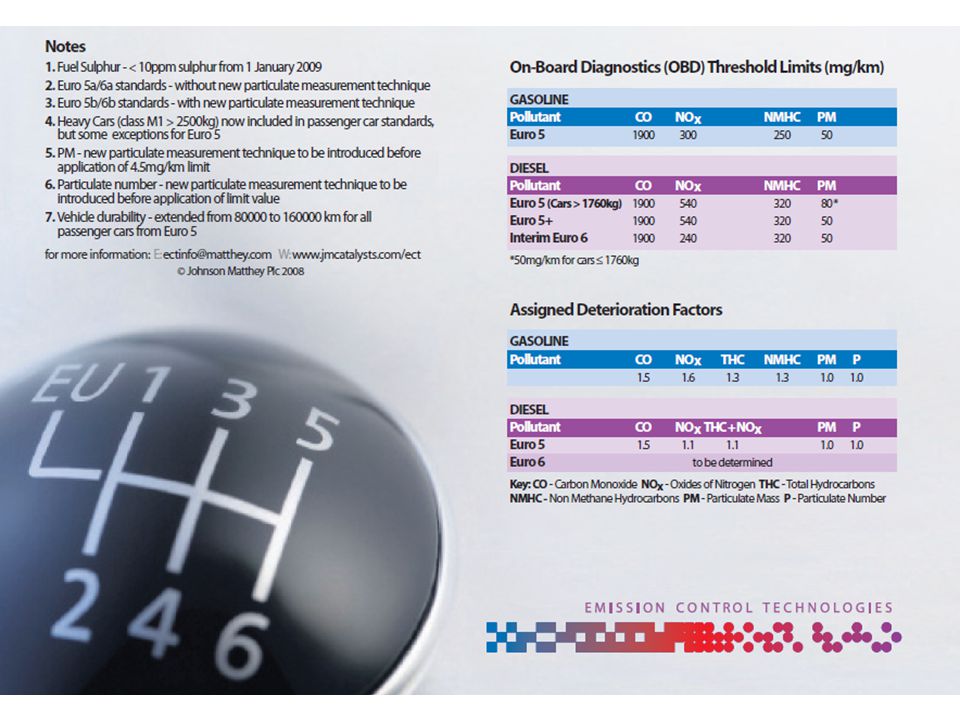
Kezdetek: California 1960-as évek, Los Angeles nyári szmog Törvények az emissziós limitekről Kisebb, hatékonyabb motorok Katalitikus konverter Fejlesztések a nagy autógyártóknál és a katalizátorgyártóknál

14
A motorban és a katalitikus konverterben végbemenő reakciók és ezek termékei

15
Üzemanyag nitrogén tartalmából
Dús zónában Termikus NO Fenimore mechanizmus szerinti NO képződés dús keverékek égésekor

16
A katalitikus konverterben lejátszódó reakciók és termékeik

18
Katalizátor nagyított képe

19
Tipikus kipuffogó katalitikus konverter felépítése

20
Gépjármű katalizátorok jellemzői
A katalitikus rendszerek igazán hatásosan csak befecskendezős motorokkal dolgoznak. Korszerû rendszerek: két katalizátorággyal működő illetve a többfunkciós katalizátorral dolgozó. Előbbinél a NO redukció történik az elsõben és az oxidációs folyamatok a másodikban, levegõ betáplálással. A többfunkciós katalizátor vezérelt motorral dolgozik, azaz oxigénszonda méri a kipufogógázok oxigéntartalmát, és ennek megfelelően változtatja a keverék összetételét. A redukáló összetételnél a katalizátorágyban lévő oxigénleadó komponensek (például ritkaföldfémoxidok) teszik tökéletessé az oxidációt. A katalizátorok fő komponensei: nemesfémek Pt/Pd, Pt/Rh, Fe, Ce oxidok, Ag vanadát. A katalizátor aktív komponenseit alumíniumoxiddal bevont kerámia monolitra viszik fel.
 teszik tökéletessé az oxidációt. A katalizátorok fő komponensei: nemesfémek Pt/Pd, Pt/Rh, Fe, Ce oxidok, Ag vanadát. A katalizátor aktív komponenseit alumíniumoxiddal bevont kerámia monolitra viszik fel.")
21
Gépkocsi kipufogó katalizátorok fejlesztési állomásai

22
Hidegindítás hatását csökkentő megoldások
1. Motorhoz közel elhelyezett katalizátor; 2. Elektromosan fűthető fém monolit; 3. Szénhidrogén csapda; 4. Kémiailag fűtött katalizátor; 5. Kipuffogó gáz égetés; 6. Előmelegítő égők; 7. Hidegindítás gyújtás késleltetéssel vagy kipuffogó utáni égetés; 8. Égőtér változtatható szeleppel; 9. Duplafalú kipuffogó cső.

23
Szénhidrogén csapda

24
Az elektromos fűtésű katalizátor működése

25
Oxigén tárolás a háromutas katalizátorban

26
Új oxigén tároló anyag: ACZ alumíniumoxid a cérium és cirkónium oxidok között
Az ACZ és a CZ összehasonlítása a diffúziós gát alapján: (a) ACZ: a CZ szinterelődését gátolják az Al2O3 részecskék amelyek a CZ részecskék között vannak diszpergálva; (b) CZ: könnyen szinterelődik diszpergens híjján.
 ACZ: a CZ szinterelődését gátolják az Al2O3 részecskék amelyek a CZ részecskék között vannak diszpergálva; (b) CZ: könnyen szinterelődik diszpergens híjján.")
27
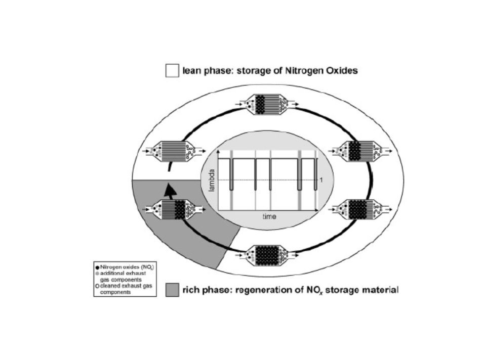
A háromutas katalizátor nem hatásos a NOx redukciójában,ha a motor sovány keverékkel üzemel (λ > 1). Sovány üzem Benzinben gazdag keverék Csak <1 s időre

28
A NOx tárolás és redukció mechanizmusa

30
A kénmérgeződés csökkentése
A TiO2 és a -Al2O3 keveréke minimalizálja a SOx lerakódást, hexagonális cella monolit hordozó növeli a szulfát eltávozást, Rh/ZrO2-hozzáadásával a katalizátor aktív lesz a hidrogén fejlesztésében vízgőz konverzióval. A bevonatok fényképe a négyzetes és a hatszögletű celláknál a monolit szerkezetben

31
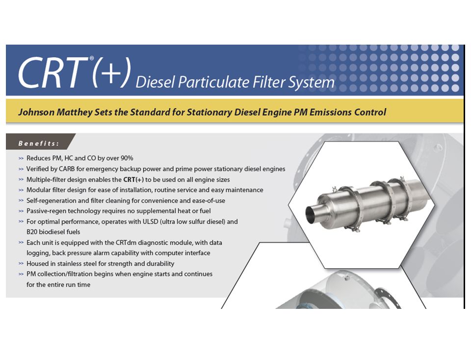
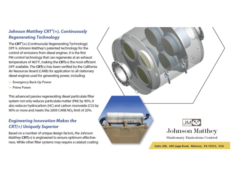
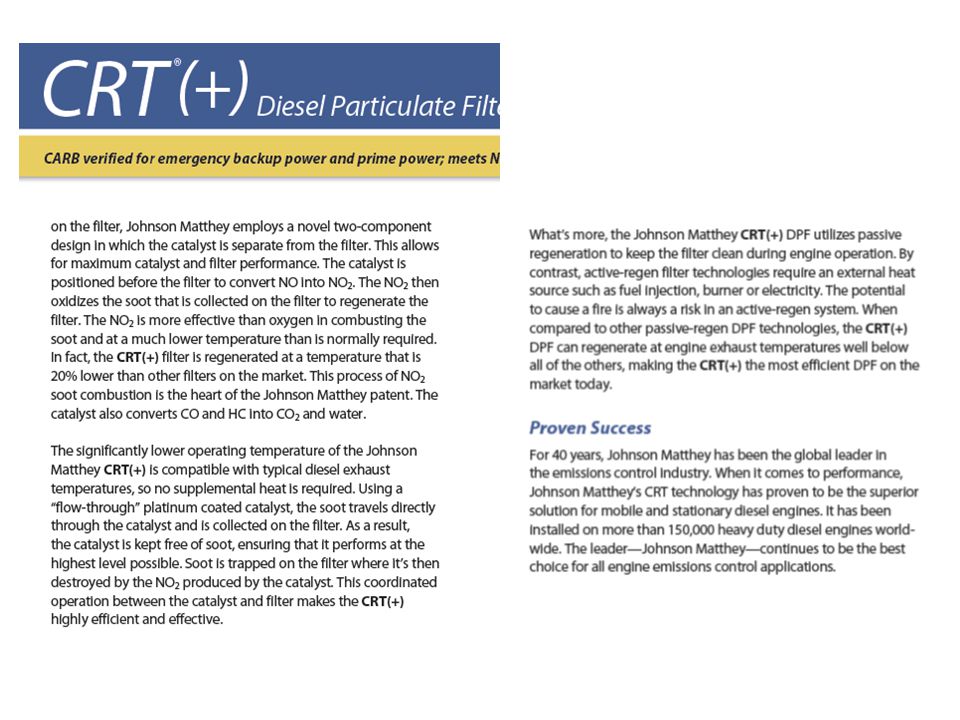
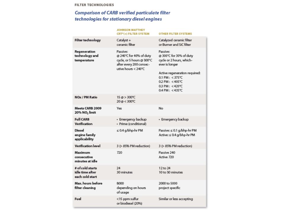
Katalizátorok a Diesel motorokhoz
Nem kívánatos reakció: A katalitikus reakciók

36
Szelektív katalitikus NO redukció

37
Diesel részecske csapda égetővel

38
Katalitikus részecske csapda

39
Toyota Hybrid Synergy Drive®
Benzin üzemű járművek CO2-t termelnek. Szén-dioxid termelődés csökkentése. Többféle megoldáson dolgoznak a HC, CO and NOX, kibocsátás csökkentésére Üzemanyag fogyasztás csökkentés másodlagos eredmény

40
PRIUS prior, to go before “Ahead of its time”
A TOYOTA Hybrid Synergy Drive jelenleg az egyetlen gyakorlatban is működő technológia az ECO jármű megalkotásához PRIUS (Latin) = prior, to go before ~ “Ahead of its time”
 = prior, to go before ~ Ahead of its time")
41
Jövő járműve Toyota Hybrid Synergy Drive®

42
Hibrid rendszerek Soros hibrid rendszer
Toyota Hybrid Synergy Drive® Hibrid rendszerek Soros hibrid rendszer Soros hibrid rendszer = “Villamos hajtású autó benzinmotor hajtotta generátorral ellátva” Benzinmotor hajtja a generátort Generátor feszültséget szolgáltat a villamos motornak a kerekek hajtásához Nincs mechanikus kapcsolat a benzinmotor és a kerekek között: A benzinmotor soha nem hajtja közvetlenül a járművet. HV Battery G Engine Inv M There are different ways of combining the two power sources in a hybrid car. In the series hybrid system, the engine runs a generator, and the generated electricity enables the electric motor to drive the wheels. This type of vehicle can be described as an electric car that is equipped with an engine-driven generator. Toyota began equipping some of its Coaster buses in Japan with a series system in In that system, a small gasoline engine operates at nearly constant rpm and drives an on-board generator to power the motor and charge the batteries. The constant rpm helps optimise combustion to minimize emissions of pollutants and maximize fuel economy. This system is also used for diesel-electric trains. Equipped with a low-output engine, the engine is operated at a practically constant speed in its most effective range, in order to efficiently recharge the battery while the vehicle is in motion.

44
Hibrid rendszerek Párhuzamos hibrid rendszer
Toyota Hybrid Synergy Drive® Hibrid rendszerek Párhuzamos hibrid rendszer Párhuzamos vagy “Lágy” hibrid rendszer Benzines és villamos motor közvetlenül hajtja a kerekeket “Lágy”: Benzinmotor szolgáltatja az elsődleges hajtó energiát Villamos motor csak rásegít amikor a kiegészítő teljesítmény vagy nyomaték szükségessé válik Villamosmotor nem tudja önállóan mozgatni a járművet! Lassítás közben: motor = generátor (tölti az akkumulátor egységet) = regeneratív fékezés HV Battery Engine Inv 12V TM MG A parallel hybrid system uses both the engine and the electric motor to directly drive the wheels is called the parallel hybrid system. This system is used by Honda (called IMA for Integrated Motor Assist). In addition to supplementing the motive force of the engine, the electric motor in this system can also serve as a generator to recharge the battery while the vehicle is in motion. A parallel or ‘mild’ hybrid system has an electric motor which cannot both assist the petrol engine and generate electricity at the same time. The result is a system where the electric motor assists the engine but isn’t capable of powering the car on its own. The Integrated Motor Assist (IMA™) power-train of Honda is a combination of a gasoline engine, an electric motor and a 5-speed manual transmission. The Honda Insight's electric motor is directly between the engine and transmission. It supplies additional power to the engine when needed and, during deceleration, uses regenerative braking to recharge the battery pack. For driving, the gasoline engine provides the primary motive power. When additional horsepower and torque are needed, such as when accelerating hard or climbing hills, the electric motor provides assist to the gasoline engine using electric current supplied by the nickel-metal hydride battery pack. During deceleration, the motor functions as a generator and recharges the battery pack. This is called regenerative braking. The voltage of the hydride battery pack of the Honda Insight is 144 V ( V).
 = regeneratív fékezés. HV Battery. Engine. Inv. 12V. TM. MG. A parallel hybrid system uses both the engine and the electric motor to directly drive the wheels is called the parallel hybrid system. This system is used by Honda (called IMA for Integrated Motor Assist). In addition to supplementing the motive force of the engine, the electric motor in this system can also serve as a generator to recharge the battery while the vehicle is in motion. A parallel or ‘mild’ hybrid system has an electric motor which cannot both assist the petrol engine and generate electricity at the same time. The result is a system where the electric motor assists the engine but isn’t capable of powering the car on its own. The Integrated Motor Assist (IMA™) power-train of Honda is a combination of a gasoline engine, an electric motor and a 5-speed manual transmission. The Honda Insight s electric motor is directly between the engine and transmission. It supplies additional power to the engine when needed and, during deceleration, uses regenerative braking to recharge the battery pack. For driving, the gasoline engine provides the primary motive power. When additional horsepower and torque are needed, such as when accelerating hard or climbing hills, the electric motor provides assist to the gasoline engine using electric current supplied by the nickel-metal hydride battery pack. During deceleration, the motor functions as a generator and recharges the battery pack. This is called regenerative braking. The voltage of the hydride battery pack of the Honda Insight is 144 V ( V).")
45
Honda IMA rendszere

46
Honda IMA rendszere

47
Honda IMA rendszere

48
Toyota Hybrid Synergy Drive® Soros/párhuzamos hibrid
“Erős” hibrid rendszer: Különálló generátor Tölti a HV akkumulátort Táplálja a villamos motort Szinergia a: korszerű villamos motor- és Benzinmotor teljesítménye között A leghatékonyabb hajtás választása: Villamos motor Benzinmotor A kettő kombinációja Regeneratív fékezés Sosem kell külső forrásból tölteni!!! 12V HV Battery MG1 Engine Inv PS MG2 The Toyota Hybrid System is a ‘strong’ hybrid system. A strong hybrid system has a separate generator that creates energy and controls the motor to drive the wheels. Unlike conventional systems in which a low-output motor temporarily boosts driving performance, Hybrid Synergy Drive achieves a synergy between enhanced motor and engine power, making the best use of both. The system continually and seamlessly selects the most efficient power to drive the vehicle: Electric motor Petrol engine Combination of both The parallel and TOYOTA system use regenerative braking. Instead of relying on an outside source of electricity, they generate their own electricity internally by reclaiming the energy that is normally wasted slowing and stopping the vehicle. It never needs to be plugged in for recharging! The benefits of Hybrid Synergy Drive : Offers “the best of both worlds”: Maximum driving performance with least impact on the environment.

49
Mi a Toyota Hybrid Synergy Drive®?
Hatékonyan ötvözi a a mozgató energia 2 típusát amely kedvezően egészíti ki egymást: Villamos motor: Nagy és állandó nyomaték, szinte 0 fordulattól Belsőégésű motor: Magas teljesítmény V. motor teljesítmény : V. motor Nyomaték : B motor nyomaték : Nyomaték Teljesítmény The TOYOTA Hybrid Synergy Drive is a type of power-train that makes a skillful use of two types of motive forces, such as an Engine and a Motor/Generator (MG2) according to the driving conditions. It maximizes the strengths of each of the motive forces and complements their weaknesses. The electromotor is very strong (high torque*), and this from standing still ! It is therefore used during take off. The engine can deliver a high power* output, but high torque is not available from standing still. During normal driving, the engine power is send to the wheels. During acceleration and at maximum speed, engine and electromotor are combined. Additional info: *Torque is a force that tends to rotate or turn things *Power is torque multiplied by the rotational speed (Power is a measure of how quickly work can be done) Jármű sebesség
 according to the driving conditions. It maximizes the strengths of each of the motive forces and complements their weaknesses. The electromotor is very strong (high torque*), and this from standing still ! It is therefore used during take off. The engine can deliver a high power* output, but high torque is not available from standing still. During normal driving, the engine power is send to the wheels. During acceleration and at maximum speed, engine and electromotor are combined. Additional info: *Torque is a force that tends to rotate or turn things. *Power is torque multiplied by the rotational speed (Power is a measure of how quickly work can be done) Jármű sebesség.")
50
Toyota Hybrid Synergy Drive® Alapvető elemek
Generátor HV akkumulátor 12V Belsőégésű Motor HV Battery MG1 Nyomaték-osztó egység (bolygómű egység) Inverter Engine Inv System diagram. Power split device Electric motor Generator Differential gear unit are all integrated in the Hybrid transaxle. Additional info: Power split device is the”hart” of the system. It distributes the different types of power. PS MG2 Differenciálmű Motor
 Inverter. Engine. Inv. System diagram. Power split device. Electric motor. Generator. Differential gear unit. are all integrated in the Hybrid transaxle. Additional info: Power split device is the hart of the system. It distributes the different types of power. PS. MG2. Differenciálmű. Motor.")
51
Toyota Hybrid Synergy Drive® Alapvető elemek
Belsőégésű motor 1.5-liter, 16-szelep, DOHC VVT-i Atkinson ciklusú benzinmotor (speciális VVT-i hangolás magas sűrítési arány mellett) Magas termikus hatásfok Speciális fejlesztés a hibrid rendszerhez Európai Step IV-es emisszió The TOYOTA PRIUS uses a 1.5-liter, 16-valve, DOHC VVT-i Atkinson cycle gasoline engine*. Atkinson cycle = High expansion ratio cycle: Special VVT-i tuning (short compression/expansion of fuel mixture) Short compression stoke is compensated by high compression ratio (13,0 : 1). High thermal efficiency. Specially developed for hybrid system. Certified European Step IV emission regulation. (but does even better!) *Additional info: Proposed by an English engineer named James Atkinson, this thermal cycle enables the compression stroke and the expansion stroke of the mechanism to be set independently of each other. Later, this concept was realized by the American R.H. Miller, who developed a system called the Miller cycle, in which the opening and closing time of the intake valves was made adjustable (this can be done with our VVT-i system). Because this system does not generate high power output, there is no practical application for this system, unless it is combined with a supercharger. However, this system offers a high level of thermal efficiency. On Prius, this weak point can be covered by combining the Atkinson cycle engine with an electric motor in the THS system.
 Magas termikus hatásfok. Speciális fejlesztés a hibrid rendszerhez. Európai Step IV-es emisszió. The TOYOTA PRIUS uses a 1.5-liter, 16-valve, DOHC VVT-i Atkinson cycle gasoline engine*. Atkinson cycle = High expansion ratio cycle: Special VVT-i tuning (short compression/expansion of fuel mixture) Short compression stoke is compensated by high compression ratio (13,0 : 1). High thermal efficiency. Specially developed for hybrid system. Certified European Step IV emission regulation. (but does even better!) *Additional info: Proposed by an English engineer named James Atkinson, this thermal cycle enables the compression stroke and the expansion stroke of the mechanism to be set independently of each other. Later, this concept was realized by the American R.H. Miller, who developed a system called the Miller cycle, in which the opening and closing time of the intake valves was made adjustable (this can be done with our VVT-i system). Because this system does not generate high power output, there is no practical application for this system, unless it is combined with a supercharger. However, this system offers a high level of thermal efficiency. On Prius, this weak point can be covered by combining the Atkinson cycle engine with an electric motor in the THS system.")
52
Toyota Hybrid Synergy Drive® Alapvető elemek
Hibrid Hajtómű CVT mintájára (Constant Variable Transaxle) Nincs zajos szíj = „okos” hajtómű nyomatékosztó egységgel (bolygómű egység) Összekapcsolja a: Benzinmotort generátort Villamos motort & kerekeket The Hybrid Transaxle acts as a CVT (Constant Variable Transmission) Compared to a conventional CVT (Constant Variable Transaxle), this transaxle has no noisy drive belts. In stead, it uses - like in a conventional automatic transaxles - a planetary gear set. But, in contrast with other automatic transaxles, shifting is step-less. The power split device (a planetary gear set) of the Hybrid Transaxle is the heart of the Toyota Prius. It’s a clever gearbox that hooks the gasoline engine, generator and electric motor together. Additional info: The power split device is a planetary gear set. The electric motor is connected to the ring gear of the gear set. It is also directly connected to the differential, which drives the wheels. So, whatever speed the electric motor and ring gear spin at, determines the speed of the car. The generator is connected to the sun gear of the gear set, and the engine is connected to the planetary carrier. The speed of the ring gear (and as a result the speed of the car) depends on all three components, so they all have to work together at all times to control the output (vehicle) speed. PS
 Nincs zajos szíj. = „okos hajtómű nyomatékosztó egységgel (bolygómű egység) Összekapcsolja a: Benzinmotort. generátort. Villamos motort & kerekeket. The Hybrid Transaxle acts as a CVT (Constant Variable Transmission) Compared to a conventional CVT (Constant Variable Transaxle), this transaxle has no noisy drive belts. In stead, it uses - like in a conventional automatic transaxles - a planetary gear set. But, in contrast with other automatic transaxles, shifting is step-less. The power split device (a planetary gear set) of the Hybrid Transaxle is the heart of the Toyota Prius. It’s a clever gearbox that hooks the gasoline engine, generator and electric motor together. Additional info: The power split device is a planetary gear set. The electric motor is connected to the ring gear of the gear set. It is also directly connected to the differential, which drives the wheels. So, whatever speed the electric motor and ring gear spin at, determines the speed of the car. The generator is connected to the sun gear of the gear set, and the engine is connected to the planetary carrier. The speed of the ring gear (and as a result the speed of the car) depends on all three components, so they all have to work together at all times to control the output (vehicle) speed. PS.")
53
Toyota Hybrid Synergy Drive® Alapvető elemek
Generátor / indítómotor Tölti a HV akkumulátort vagy Ellátja a villamos motort Indítja a benzinmotort Szabályozza a CVT funkciót Benzinmotor Generátor The generator (MG1) recharges the HV battery orsupplies electrical power to drive the electrical motor (MG2). It also serves as a starter motor to start the engine. In addition - by regulating the amount of electrical power generated (thus varying the generator’s rpm) - the generator (MG1) effectively controls the Continuously Variable Transmission (CVT) function of the transaxle. Additional info: Due to the high maximum rpm from of rpm, the generator has a very high charging capacity.
 recharges the HV battery orsupplies electrical power to drive the electrical motor (MG2). It also serves as a starter motor to start the engine. In addition - by regulating the amount of electrical power generated (thus varying the generator’s rpm) - the generator (MG1) effectively controls the Continuously Variable Transmission (CVT) function of the transaxle. Additional info: Due to the high maximum rpm from of rpm, the generator has a very high charging capacity.")
54
Toyota Hybrid Synergy Drive® Alapvető elemek
Hajtó villamos motor / Generátor Hajtja a járművet Végrehajtja a regeneratív fékezést Max. teljesítmény: 50 kW Max. nyomaték: 400 Nm ! Álló helyzetből Széles skálán Motor When the vehicle is started-off and during acceleration the electric motor drives the vehicle to achieve excellent dynamic performance. During deceleration, the electric motor converts the vehicle’s kinetic energy (motion) into electrical energy, which is then stored in the HV battery (regenerative braking). The new high-output electric motor developed exclusively by Toyota produces a high level of power (50 kW ) with the world’s highest level of output to weight/volume. With 400 Nm of torque, the new electric motor delivers torque to compete with V6 diesel power plants. (The wide maximum torque distribution range (0 – 1200 rpm) allows the vehicle to run till a relatively high speed on only electric power). Additional info: The ultra-efficient electric motor is now more powerful than most to 1.2-litre internal combustion engines in the market (50kW (68hp) / 1,040-5,600rpm) and features an amount of torque which is enough to surpass the values produced by V6 diesels (400Nm / 0-1,200rpm). Reference: Max. output 1,0 l Yaris engine : 48 kW / 6000 rpm Max. torque 2,0 l Avensis Common-rail diesel engine: 280 Nm / 2000 – 2200 rpm
 into electrical energy, which is then stored in the HV battery (regenerative braking). The new high-output electric motor developed exclusively by Toyota produces a high level of power (50 kW ) with the world’s highest level of output to weight/volume. With 400 Nm of torque, the new electric motor delivers torque to compete with V6 diesel power plants. (The wide maximum torque distribution range (0 – 1200 rpm) allows the vehicle to run till a relatively high speed on only electric power). Additional info: The ultra-efficient electric motor is now more powerful than most 1.0- to 1.2-litre internal combustion engines in the market (50kW (68hp) / 1,040-5,600rpm) and features an amount of torque which is enough to surpass the values produced by V6 diesels (400Nm / 0-1,200rpm). Reference: Max. output 1,0 l Yaris engine : 48 kW / 6000 rpm. Max. torque 2,0 l Avensis Common-rail diesel engine: 280 Nm / 2000 – 2200 rpm.")
55
Toyota Hybrid Synergy Drive® Alapvető elemek
Nyomatékosztó egység = bolygómű (a rendszer lelke…) Összekapcsolja a benzinmotort és a két villamos gépet Elosztja a benzinmotor teljesítményét: A kerekek felé Generátor felé Motor Generátor MG2 The Power Split Device is the “heart” of the system. The electric motor (together with the wheels) and the generator are mechanically joined via a planetary gear unit (Power split device) The Power Split Device divides the power output of the engine into the motive force directed to the drive wheels and the drive force to the generator (MG1) for generating electricity. MG1 b.motor Nyomatékosztó egység (bolygómű egység)
 Összekapcsolja a benzinmotort és a két villamos gépet. Elosztja a benzinmotor teljesítményét: A kerekek felé. Generátor felé. Motor. Generátor. MG2. The Power Split Device is the heart of the system. The electric motor (together with the wheels) and the generator are mechanically joined via a planetary gear unit (Power split device) The Power Split Device divides the power output of the engine into the motive force directed to the drive wheels and the drive force to the generator (MG1) for generating electricity. MG1. b.motor. Nyomatékosztó egység (bolygómű egység)")
56
Toyota Hybrid Synergy Drive® Alapvető elemek
HV akkumulátor A csomagtérben a hátsó ülés mögött Emellett 408 l csomagtér kapacitás Magas belső ellenállás (teljesen töltött akkumulátor 60 napig tartja a töltését) The HV battery is rigidly mounted inside trunk to the floor pan cross member behind the rear seat (safe location). Although the luggage compartment has a generous capacity of 408 l. The battery has a high voltage of V DC. It has a low static current drop. (A fully charged battery can hold his charge for 60 days) Although, if you do not use the vehicle for a long time, it’s recommended to charge the batteries (HV & 12 V), once every 2 weeks, for about 30 minutes, by starting the hybrid system (READY light ON) with all electrical components turned off (A/C !). Additional info: There is an air vent for the battery pack on the side of the right rear seat. It is important not to block this vent, or the battery may overheat, resulting in reduced performance. HV akkumulátor egység
 The HV battery is rigidly mounted inside trunk to the floor pan cross member behind the rear seat (safe location). Although the luggage compartment has a generous capacity of 408 l. The battery has a high voltage of V DC. It has a low static current drop. (A fully charged battery can hold his charge for 60 days) Although, if you do not use the vehicle for a long time, it’s recommended to charge the batteries (HV & 12 V), once every 2 weeks, for about 30 minutes, by starting the hybrid system (READY light ON) with all electrical components turned off (A/C !). Additional info: There is an air vent for the battery pack on the side of the right rear seat. It is important not to block this vent, or the battery may overheat, resulting in reduced performance. HV akkumulátor egység.")
57
Toyota Hybrid Synergy Drive® Alapvető elemek
HV akkumulátor Szigetelt Nikkel metal hydride (Ni-MH) akkumulátor Modul (6 Cella) The HV battery is a sealed nickel hydride (Ni-MH) battery. It consists of 168 cells of 1.2 V, grouped by 28 modules of 6 cells. 168 cells x 1,2 V = V DC The batteries are jointly developed and produced with TOYOTA’s partner, Panasonic. Additional info: HV battery capacity: 6,5 Ah (3 hr rating) The electrolyte of the HV battery consists mainly of potassium hydroxide (KOH) and sodium hydroxide (NaOH) The electrolyte is absorbed into the battery cell plates and form a gel that normally will not leak, even in a collision. HV battery modules are non-spillable and sealed in a plastic case and well protected (rigidly mounted to the luggage floor pan cross member behind the rear seat), but KOH and NaOH are corrosive and may cause serious burns. It is harmful by ingestion, inhalation and in contact with skin. If the electrolyte comes into contact with the eyes, serious eye damage may result. The metal case of the HV battery is isolated from high voltage and concealed by fabric liner in the luggage compartment. In the unlikely event the battery pack is overcharged, the modules vent gases are directed outside the vehicle through a vent hose connected to each NIMH battery module. Cella (1,2 V) Szerviz csatlakozó 28 modul
 akkumulátor. Modul (6 Cella) The HV battery is a sealed nickel hydride (Ni-MH) battery. It consists of 168 cells of 1.2 V, grouped by 28 modules of 6 cells. 168 cells x 1,2 V = V DC. The batteries are jointly developed and produced with TOYOTA’s partner, Panasonic. Additional info: HV battery capacity: 6,5 Ah (3 hr rating) The electrolyte of the HV battery consists mainly of potassium hydroxide (KOH) and sodium hydroxide (NaOH) The electrolyte is absorbed into the battery cell plates and form a gel that normally will not leak, even in a collision. HV battery modules are non-spillable and sealed in a plastic case and well protected (rigidly mounted to the luggage floor pan cross member behind the rear seat), but KOH and NaOH are corrosive and may cause serious burns. It is harmful by ingestion, inhalation and in contact with skin. If the electrolyte comes into contact with the eyes, serious eye damage may result. The metal case of the HV battery is isolated from high voltage and concealed by fabric liner in the luggage compartment. In the unlikely event the battery pack is overcharged, the modules vent gases are directed outside the vehicle through a vent hose connected to each NIMH battery module. Cella (1,2 V) Szerviz csatlakozó. 28 modul.")
58
Energia gazdálkodás Toyota Hybrid Synergy Drive®
+ - : Mozgató erő HV akkumulátor HV battery HV akkumulátor Regeneratív fékezés HV akkumulátor : B.motor hajtóerő HV akkumulátor Kisütés Töltés Elindulás Jármű áll Energia B.Motor leáll gyorsítás Kisütés Töltés Haladás A feature that made a difference between TOYOTA Hybrid Synergy Drive System and other competitor hybrid systems was its ability for choosing the most suitable operating mode for every situation, ranging from entirely electric power (for top efficiency) to engine+motor+battery power (for performance). In this graph, the red line shows the energy required to move the car, while the blue line shows energy produced by the engine. When the car stops, the gasoline engine stops too, instead of just idling and wasting energy. During starting out and at low speed, gasoline engine efficiency is low, so the car runs on its electric motor, on electricity from the HV battery. The electric motor is very strong (high torque) from standing still. At faster speeds, the gasoline engine propels the vehicle. But the system gives priority to operating the engine only within its most efficient rpm range, so engine power may not be sufficient when the car accelerates. At such times, therefore, the motor provides assistance to make up for the shortage, drawing electricity from the secondary battery (yellow area). (0-100 km/h acceleration below 11-second barrier) If the car cruises at a steady speed, the engine, which operates with priority placed on efficiency, may produce more energy than is needed. In this case, such excess energy is used to generate electricity, which is stored in the secondary battery (light green area). During deceleration (when the accelerator is let up on to slow down), the engine stops automatically to avoid wasting energy. And during deceleration through braking and other means, the car's forward momentum is used to generate electricity, which is stored in the secondary battery (green area). All these features combine to form the backdrop to the pursuit of the world’s best fuel efficiency. B.motor áll B.Motor beindul Fékezés Lassítás idő
 to engine+motor+battery power (for performance). In this graph, the red line shows the energy required to move the car, while the blue line shows energy produced by the engine. When the car stops, the gasoline engine stops too, instead of just idling and wasting energy. During starting out and at low speed, gasoline engine efficiency is low, so the car runs on its electric motor, on electricity from the HV battery. The electric motor is very strong (high torque) from standing still. At faster speeds, the gasoline engine propels the vehicle. But the system gives priority to operating the engine only within its most efficient rpm range, so engine power may not be sufficient when the car accelerates. At such times, therefore, the motor provides assistance to make up for the shortage, drawing electricity from the secondary battery (yellow area). (0-100 km/h acceleration below 11-second barrier) If the car cruises at a steady speed, the engine, which operates with priority placed on efficiency, may produce more energy than is needed. In this case, such excess energy is used to generate electricity, which is stored in the secondary battery (light green area). During deceleration (when the accelerator is let up on to slow down), the engine stops automatically to avoid wasting energy. And during deceleration through braking and other means, the car s forward momentum is used to generate electricity, which is stored in the secondary battery (green area). All these features combine to form the backdrop to the pursuit of the world’s best fuel efficiency. B.motor áll. B.Motor beindul. Fékezés. Lassítás. idő.")
59
Toyota Hybrid Synergy Drive® Működés
Energiafolyam megjelenítése A nyilak az energiafolyam irányát mutatják: narancs (benzin motor) sárga (villamos motor/generátor) Visszatáplált energia: Megforduló nyílirány Nyíl színe zöldre vált Visszamaradó HV akk. töltöttség: zöld = töltött piros = kisütött Energy monitor screen (on Multi Display) Vehicle driving condition, hybrid system operating condition and energy recovery condition are shown. Indicates the flow of energy by orange (engine) and yellow (electric motor/generator) arrows. While the energy is recovered, the arrows change the pointing direction and turn green. Indicates the remaining capacity of the hybrid vehicle battery. Green = charged Red = discharged The screen display updates every 2 seconds, so it may not coincide with the actual status.
 sárga (villamos motor/generátor) Visszatáplált energia: Megforduló nyílirány. Nyíl színe zöldre vált. Visszamaradó HV akk. töltöttség: zöld = töltött. piros = kisütött. Energy monitor screen (on Multi Display) Vehicle driving condition, hybrid system operating condition and energy recovery condition are shown. Indicates the flow of energy by orange (engine) and yellow (electric motor/generator) arrows. While the energy is recovered, the arrows change the pointing direction and turn green. Indicates the remaining capacity of the hybrid vehicle battery. Green = charged. Red = discharged. The screen display updates every 2 seconds, so it may not coincide with the actual status.")
60
Toyota Hybrid Synergy Drive® Vezérlés
Villamos hajtás mód (EV mód) A benzinmotor működtetése késleltetett Normál EV Mód EV mód felfüggesztése EV mód kapcsoló ismételt megnyomása HV akkumulátor töltöttsége alacsony HV akkumulátor hőm. kicsi vagy nagy A benzinmotor bemelegítése tart Járműsebesség bizonyos mértéket meghalad A gázpedál bizonyos helyzetet elér With the improvement of motor efficiency and increased contribution of electric power, the engine can be completely stopped when it encounters poor efficiency, broadening the range in which the car is run on power generated by the motor alone. By pushing the EV switch, the activation of the engine is delayed (longer use of electric motor). The EV indicator light turns ON. (You can click left and right picture to see the movies)* Reference: The EV mode will become OFF after running for approx. 1 km (0.6 mile) at less than 45 km/h (28 mph) on a level road, with the standard state of charge (SOC) of the HV battery. * First delete the picture on top of the right movie vagy
 A benzinmotor működtetése késleltetett. Normál. EV Mód. EV mód felfüggesztése. EV mód kapcsoló ismételt megnyomása. HV akkumulátor töltöttsége alacsony. HV akkumulátor hőm. kicsi vagy nagy. A benzinmotor bemelegítése tart. Járműsebesség bizonyos mértéket meghalad. A gázpedál bizonyos helyzetet elér. With the improvement of motor efficiency and increased contribution of electric power, the engine can be completely stopped when it encounters poor efficiency, broadening the range in which the car is run on power generated by the motor alone. By pushing the EV switch, the activation of the engine is delayed (longer use of electric motor). The EV indicator light turns ON. (You can click left and right picture to see the movies)* Reference: The EV mode will become OFF after running for approx. 1 km (0.6 mile) at less than 45 km/h (28 mph) on a level road, with the standard state of charge (SOC) of the HV battery. * First delete the picture on top of the right movie. vagy.")
61
Toyota Hybrid Synergy Drive® Vezérlés
Villamos hajtás mód EV mód kapcsolója pillanatkapcsoló típusú EV mód bekapcsolva: +/- 1 km < 45 km/h síkúton (általános töltöttség esetén) EV mode switch is a momentary switch EV mode ON: +/- 1 km < 45 km/h on a level road (with standard state of charge of the HV battery) Additional info: HV battery capacity: 6,5 Ah (3 hr rating), (201,6 V ! 6,5 Ah x 201,6 V = 1304 Wh = 1,3 kWh electrical energy) (for a battery weight of only 39 kg) 12 V battery capacity: 36 Ah (5 hr rating) with Smart key, 28 Ah without Smart key (only 12 V ! 36 Ah x 12 V = 432 Wh = 0,43 kWh electrical energy) (= only 33 % of HV battery !) RAV 4 EV HV battery capacity: 90 Ah (5 hr rating) (288 V ! 90 Ah x 288 V = kWh = 25,9 kWh electrical energy) (20 x electrical energy of Prius HV battery, but battery weight is 450 kg !) Fuel tank capacity: 45 l Fuel consumption (combined): 4,3 l/100 km CO2 emissions: 104 g/km EV mód kapcsolója
 EV mode switch is a momentary switch. EV mode ON: +/- 1 km < 45 km/h on a level road (with standard state of charge of the HV battery) Additional info: HV battery capacity: 6,5 Ah (3 hr rating), (201,6 V ! 6,5 Ah x 201,6 V = 1304 Wh = 1,3 kWh electrical energy) (for a battery weight of only 39 kg) 12 V battery capacity: 36 Ah (5 hr rating) with Smart key, 28 Ah without Smart key (only 12 V ! 36 Ah x 12 V = 432 Wh = 0,43 kWh electrical energy) (= only 33 % of HV battery !) RAV 4 EV HV battery capacity: 90 Ah (5 hr rating) (288 V ! 90 Ah x 288 V = kWh = 25,9 kWh electrical energy) (20 x electrical energy of Prius HV battery, but battery weight is 450 kg !) Fuel tank capacity: 45 l. Fuel consumption (combined): 4,3 l/100 km. CO2 emissions: 104 g/km. EV mód kapcsolója.")
62
Toyota Hybrid Synergy Drive® Hatásfok
EV mode switch is a momentary switch EV mode ON: +/- 1 km < 45 km/h on a level road (with standard state of charge of the HV battery) Additional info: HV battery capacity: 6,5 Ah (3 hr rating), (201,6 V ! 6,5 Ah x 201,6 V = 1304 Wh = 1,3 kWh electrical energy) (for a battery weight of only 39 kg) 12 V battery capacity: 36 Ah (5 hr rating) with Smart key, 28 Ah without Smart key (only 12 V ! 36 Ah x 12 V = 432 Wh = 0,43 kWh electrical energy) (= only 33 % of HV battery !) RAV 4 EV HV battery capacity: 90 Ah (5 hr rating) (288 V ! 90 Ah x 288 V = kWh = 25,9 kWh electrical energy) (20 x electrical energy of Prius HV battery, but battery weight is 450 kg !) Fuel tank capacity: 45 l Fuel consumption (combined): 4,3 l/100 km CO2 emissions: 104 g/km
 Additional info: HV battery capacity: 6,5 Ah (3 hr rating), (201,6 V ! 6,5 Ah x 201,6 V = 1304 Wh = 1,3 kWh electrical energy) (for a battery weight of only 39 kg) 12 V battery capacity: 36 Ah (5 hr rating) with Smart key, 28 Ah without Smart key (only 12 V ! 36 Ah x 12 V = 432 Wh = 0,43 kWh electrical energy) (= only 33 % of HV battery !) RAV 4 EV HV battery capacity: 90 Ah (5 hr rating) (288 V ! 90 Ah x 288 V = kWh = 25,9 kWh electrical energy) (20 x electrical energy of Prius HV battery, but battery weight is 450 kg !) Fuel tank capacity: 45 l. Fuel consumption (combined): 4,3 l/100 km. CO2 emissions: 104 g/km.")
63
Toyota Prius III 2010 EPA becsült üzemanyag fogyasztás 50 mf/gallon 4,85 liter/100 km. Motor 1.8 liter, összteljesítmény 134 lóerő

64
Tüzelőanyagcellák Fuel cells
A tüzelőanyagcella két elektródból és a köztük lévő elektrolitból áll. Az egyik elektródhoz oxigént, a másikhoz hidrogént vezetve elektromos áramot, hőt és vizet termel. A hidrogént vezetjük az anódhoz, az oxigént a katódhoz. Az elektródok katalitikusan aktív anyagot tartalmaznak, ezen a hidrogén protonná és elektronná alakul. A proton áthalad az elektroliton és a katódon az oxigénnel és az áramkörön át megérkező elektronnal vízzé alakul.

66
A tüzelőanyagcella és a hagyományos Carnot ciklus hatásfoka a hőmérséklet függvényében

67
Tüzelőanyagcella hatásfoka
Termodinamikai hatásfok: efftd = G/H G = - n*F*E ahol n az elektronszáma a folymatnak, F a Faraday konstans (96500 A*s) E az elméleti cellapotenciál. Ebből levezethető az elektrokémiai hatásfok: effel = V/E ahol V a cellafeszültség. A hidrogén-oxigén cellára 25oC-on a megfelelő értékek: H = -287 kJ/mol, G = -238 kJ/mol, S = -164 JK-1mol-1, n = 2 Ezekből az értékekből számolva efftd = 0,83, E = 1,23V Terhelés alatt (100mA/cm2) a cella feszültség kb. 0,85V lehet. Ebből az elektrokémiai hatásfok: effel = Vterh/E = 0,85/1,23 = 0,69 A termikus hatásfokot úgy kapjuk, hogy kiszámoljuk a hidrogén-oxigén reakció entalpiájából a vonatkozó feszültséget: (287 kJ/mol)/(2*96,5 kA*s) = 1,5V 0,85/1,5 = 0,57
 E az elméleti cellapotenciál. Ebből levezethető az elektrokémiai hatásfok: effel = V/E. ahol V a cellafeszültség. A hidrogén-oxigén cellára 25oC-on a megfelelő értékek: H = -287 kJ/mol, G = -238 kJ/mol, S = -164 JK-1mol-1, n = 2. Ezekből az értékekből számolva efftd = 0,83, E = 1,23V. Terhelés alatt (100mA/cm2) a cella feszültség kb. 0,85V lehet. Ebből az elektrokémiai hatásfok: effel = Vterh/E = 0,85/1,23 = 0,69. A termikus hatásfokot úgy kapjuk, hogy kiszámoljuk a. hidrogén-oxigén reakció entalpiájából a vonatkozó feszültséget: (287 kJ/mol)/(2*96,5 kA*s) = 1,5V 0,85/1,5 = 0,57.")
68
Alkálikus elektrolittal a következő reakciók játszódnak le:
A katódon: O2 + 2 H2O + 4 e- 4 OH- Az anódon: 2 H2 + 4 OH- 4 H2O + 4 e- A bruttó reakció: 2 H2 + O2 2 H2O Savas elektrolittal a következő reakciók játszódnak le: A katódon: ½ O2 + 2 H+ + 2 e- H2O Az anódon: H2 2 H+ + 2 e- A bruttó reakció: H2 + ½ O2 H2O

69
Az energia átalakítás hatásfoka az erőmű nagyságától függően összehasonlítva polimer savas elektrolitos és szilárd oxidos tüzelőanyagcellákéval

70
Proton cserélő membrán cella: Nafion membrán, elektrokatalizátor, porózus karbon elektródon.

72
TEM-kép a 20 t.% Pt3Sn/Vulcan E-TEK katalizátorról

73
A tüzelőanyag cellák osztályozása
Direkt Indirekt Közvetlenül oxidálják az üzemanyagot Előzetes üzemanyag átalakítással működnek, ez csökkenti a hatásfokot Működési hőmérséklet szerint: Nagy közepes alacsony Működési nyomás szerint: Az üzemanyag és az oxidálószer szerint: Gázalakú reaktánsok (hidrogén, ammónia, levegő, oxigén) Folyadék üzemanyagok (alkoholok, hidrazin, szénhidrogének) Szilárd üzemanyagok (szén, hidridek) Elektrolit szerint: Lúgos cellák (AFC). Foszforsavas cellák (PAFC). Karbonát olvadékos cellák (MCFC). Szilárd oxid cellák (SOFC). Protoncserélő membrános cellák (PEMFC). Az elektrolit lehet folyadék halmazállapotú, ezek a mobil elektrolitos rendszerek, ha az elektrolit szilárd mátrixba van felitatva, akkor ezeket immobil vagy mátrix rendszereknek hívják. AFC: KOH oldat elektrolit, CO2 mentes üzemanyagot és levegőt igényel. Az elektródok lehetnek nikkel, vagy platina fémmel készültek, a katód szénből és műanyagból.
 Folyadék üzemanyagok (alkoholok, hidrazin, szénhidrogének) Szilárd üzemanyagok (szén, hidridek) Elektrolit szerint: Lúgos cellák (AFC). Foszforsavas cellák (PAFC). Karbonát olvadékos cellák (MCFC). Szilárd oxid cellák (SOFC). Protoncserélő membrános cellák (PEMFC). Az elektrolit lehet folyadék halmazállapotú, ezek a mobil elektrolitos rendszerek, ha az elektrolit szilárd mátrixba van felitatva, akkor ezeket immobil vagy mátrix rendszereknek hívják. AFC: KOH oldat elektrolit, CO2 mentes üzemanyagot és levegőt igényel. Az elektródok lehetnek nikkel, vagy platina fémmel készültek, a katód szénből és műanyagból.")
74
MCFC: anód porózus nikkel, oxidokkal keverve, a katód lítium tartalmú szinterelt nikkel-oxid. Az elektrolit Li-K karbonát, lítium-aluminát mátrixban, a cellák bipoláris konfigurációjúak. Működési hőmérséklet kb. 700oC. Tipikus elektród reakciók: Anódon H2 + CO32- H2O + CO2 +2 e- Katódon ½ O2 + CO2 +2 e- CO32- PAFC: elektrolit foszforsav szilíciumkarbid mátrixban, elektródok Pt/C/PTFE, bipoláris lemezek grafit-műanyag kompozitokból készülnek. Ezek a cellák átalakított üzemanyaggal is működnek, mert a széndioxid és a szénmonoxid nem zavarnak. PEMFC: elektrolit lemez szulfonált politetrafluoretilén. SOFC: elektrolit Y2O3 és ZrO2 keveréke, működési hőmérséklet 1000oC. Anódos reakciók: H2 + O2- H2O + 2 e- CO + O2- CO2 + 2 e- Katódos reakció: ½ O2 + 2 e- O2- Anód anyaga Ni/ZrO2, katód anyaga LaMnO3.

75
Kereskedelmi tüzelőanyagcella összeállítások
1200W-16kW

76
Mi kell az ÖKO autóhoz? Tüzelőanyagcellás jármű, megfelelő hidrogén tárolási kapacitással. Olcsón előállítható hidrogén, amit bárhol tankolhatunk, mint most a benzint vagy gázolajat. Elektromos hajtású autó, nagy fajlagos kapacitású akkumulátorral, olcsó elektromos áram megújuló forrásból

77
Hidrogén előállítási lehetőségek
Fosszilis Megújuló

78
Fotóelektrolízis

79
Foto-bio hidrogén előállítás

80
A jód-kén ciklusok Korróziós problémák!!!

81
Hidrogén tárolás Gáz formában: elérhető, drága, szénszálas anyagokkal,
6-10 t% H bar Folyadék állapotban: elérhető, drága, mélyhűtés Dewar edényekben 20 t% H2 1 bar -253 oC Szilárd állapotban: hidridekben, fémötvözetekben, szén nanocsövekben, távol a megvalósítástól 9 t% H bar

82
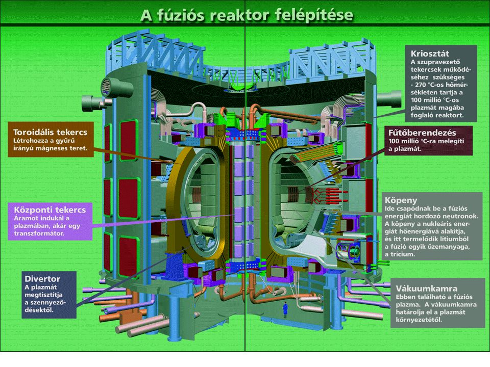
A távolabbi jövő: az ITER

83
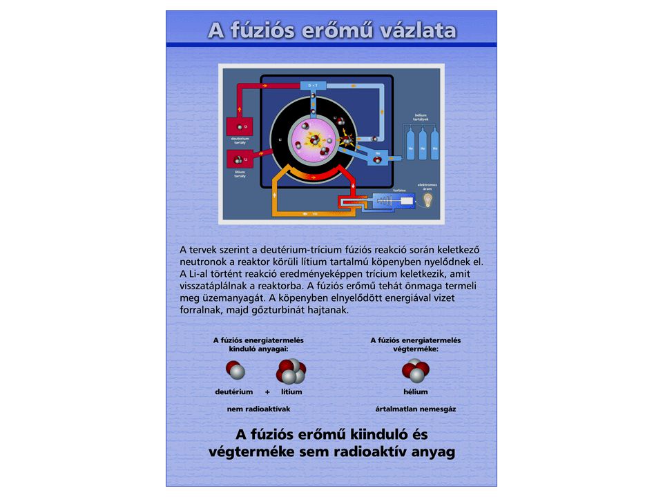
A fúziós reakció

87
Szükségünk van-e hidrogén, metanol, -valerolakton stb. gazdaságra?
Átalakítsuk a megtermelt elektromos energiát veszteséggel kémiai energia hordozóvá? Majd szintén veszteséggel alakítsuk vissza elektromos majd mechanikai energiává? Másik megoldás, hogy tároljuk minél kisebb tömegű tárolóban (akkumulátor, kapacitor), ami sokszor feltölthető és abból nyerjük vissza sokkal jobb hatásfokkal az elektromos energiát?
, ami sokszor feltölthető és abból nyerjük vissza sokkal jobb hatásfokkal az elektromos energiát")
88
Az energia probléma nagyságrendje
Frankfurt Airport (2004) 520 gép indul naponta, 50 Jumbo Jets (Boeing 747) 130 t kerozin per Jumbo = 50 t folyékony hidrogén A napi 50 Jumbo Jet kiszolgálásához: (2,500 t LH2/nap, 36,000 m3 LH2/nap, ehhez 22,500 m3 víz/nap) Az elektrolízis, cseppfolyósítás, szállítás és töltés 8 db 1GW erőmű folyamatos működését igényli! Legalább 25 nukleáris erőmű és Frankfurt teljes vízfogyasztása kell az 520 jet kiszolgálásához a Frankfurt Airport-on. Az energia probléma nagyságrendje (egy “megrázó” példa) Az energia probléma nem oldható meg azzal, hogy a fosszilis tüzelőanyagokról átállunk hidrogénre! Ulf Bossel – October 2005
 520 gép indul naponta, 50 Jumbo Jets (Boeing 747) 130 t kerozin per Jumbo = 50 t folyékony hidrogén. A napi 50 Jumbo Jet kiszolgálásához: (2,500 t LH2/nap, 36,000 m3 LH2/nap, ehhez 22,500 m3 víz/nap) Az elektrolízis, cseppfolyósítás, szállítás és töltés 8 db 1GW erőmű folyamatos működését igényli! Legalább 25 nukleáris erőmű és Frankfurt teljes vízfogyasztása kell az 520 jet kiszolgálásához a Frankfurt Airport-on. Az energia probléma nagyságrendje. (egy megrázó példa) Az energia probléma nem oldható meg azzal, hogy a fosszilis tüzelőanyagokról átállunk hidrogénre! Ulf Bossel – October")
89
Jövő fenntartható energiával
? ? ? Belép Hidrogén megyébe Elhagyja Benzin megyét Ulf Bossel – October 2005

90
“Creation” of “Hydrogen Energy” (1)
From water by electrolysis H2O => H2 + ½ O2 Species balance 2 hydrogen atoms = 2 hydrogen atoms 1 oxygen atom = 1 oxygen atom Simple equations, friendly elements H, O and C Hydrogen promoters are happy! Even politicians can follow and initiate hydrogen programs 2. From natural gas by reforming CH4 + 2 H2O => 4 H2 + CO2 Species balance 1 carbon atom = 1 carbon atom 8 hydrogen atoms = 8 hydrogen atoms 2 oxygen atoms = 2 oxygen atoms Ulf Bossel – October 2005

91
“Creation” of “Hydrogen Energy” (2)
From water by electrolysis H2O => H2 + ½ O2 Mass balance 18 kg H2O = 2 kg H kg O2 9 kg H2O = 1 kg H2 + 8 kg O2 Clean water availability may limit hydrogen production Mass handling not trivial. Carbon sequestration??? 2. From natural gas by reforming CH4 + 2 H2O => 4 H2 + CO2 Mass balance 16 kg CH kg H2O = 8 kg H kg CO2 2 kg CH kg H2O = 1 kg H kg CO2 1 kg hydrogen replaces 1 Gallon or 4 Liters of gasoline Ulf Bossel – October 2005

92
“Creation” of “Hydrogen Energy” (3)
From water by electrolysis H2O => H2 + ½ O2 Energy balance electrical energy = energy in H2 286 kJ/mol = 286 kJ/mol Where does the energy come from to make and distribute hydrogen? We need to solve energy problems, not chemical problems! Reality: 130% energy input = 100% energy in H2 + 30% energy loss 2. From natural gas by reforming CH4 + 2 H2O => 4 H2 + CO2 Energy balance Methane energy + heat = energy in H2 890 kJ/mol kJ/mol = (4 x 286 kJ/mol =) 1,144 kJ/mol Reality: 110% energy input = 100% energy in H2 + 10% energy loss Add 100% for hydrogen distribution to customers Ulf Bossel – October 2005
 1,144 kJ/mol. Reality: 110% energy input = 100% energy in H2 + 10% energy loss. Add 100% for hydrogen distribution to customers. Ulf Bossel – October")
93
primary energy consumption increased more coal, more nuclear energy
more CO2 and radioactive waste time wasted global catastrophe Entering Hydrogen County Leaving Gasoline County Ulf Bossel – October 2005

94
Sustainable Energy Future Entering Physical Energy County Leaving
Chemical Energy County Ulf Bossel – October 2005

95
Common Goal: Sustainable Energy Future
Only two conditions must be satisfied: Common Goal: Sustainable Energy Future 1. Energy source, sink, handling and use must be sustainable 2. Energy must be distributed and used with highest efficiency Need to re-organize the entire energy system for a sustainable energy future Ulf Bossel – October 2005

96
Energy carriers cannot be classified as „sustainable“
Sustainable Energy Oil, natural gas, coal or nuclear are not sustainable! Energy from sustainably managed renewable sources: Solar energy photovoltaic DC electricity thermal AC electricity, hot water, space heating etc. Wind energy AC electricity Hydropower AC electricity Ocean energy waves, tides AC electricity Geothermal heat AC electricity, hot water, space heating etc. Biomass and organic waste heat, organic fuels heat AC electricity, hot water, space heating etc. Most renewable energy is “harvested” as electricity Energy carriers like water, hydrogen, electrons etc. obey the laws of species conservation. Energy carriers cannot be classified as „sustainable“ Ulf Bossel – October 2005

97
Solar Energy Availability Solar energy received by red area
exceeds World energy consumption In addition: wind, waves, geothermal, biomass, organic waste etc. Ulf Bossel – October 2005

98
Energy Challenge The challenge is the
With the exception of biomass nature provides physical energy kinetic energy of wind, water, waves solar radiation heat form geothermal sources With the exception of food people need physical energy motion communication lighting heating and cooling (space conditioning and cooking) industrial processes The challenge is the direct transfer of physical energy from source to service Whenever possible, avoid conversions across the chemical -|- physical energy boundary Ulf Bossel – October 2005
 industrial processes. The challenge is the. direct transfer of physical energy from source to service. Whenever possible, avoid conversions across the. chemical -|- physical. energy boundary. Ulf Bossel – October")
99
Energy Flux Diagram of Germany (1995)
yellow: primary energy blue: energy losses purple: useful energy Ulf Bossel – October 2005

100
Fossil Past and Sustainable Future
Fossil Energy Past Sustainable Energy Future Electricity from renewable sources Electricity from renewable sources physical Electrolysis (80%) chemical synthetic hydrogen ? hydrocarbons from fossil sources hydrocarbons from biomass Compression Liquefaction Distribution Storage transfer 40% of HHV chemical DMFC, MCFC, SOFC Carnot machines H2 fuel cells (50%) physical overall efficiency: (35%) (90%) (50%) (90%) (25%) Consumers need motion, sound, light, heat, communication Ulf Bossel – October 2005
 chemical. synthetic. hydrogen. hydrocarbons. from. fossil sources. hydrocarbons. from. biomass. Compression. Liquefaction. Distribution. Storage. transfer. 40% of. HHV. chemical. DMFC, MCFC, SOFC. Carnot machines. H2 fuel cells (50%) physical. overall efficiency: (35%) (90%) (50%) (90%) (25%) Consumers need motion, sound, light, heat, communication. Ulf Bossel – October")
101
Electricity Transport
Renewable Source Energy Consumer by electrons 100% 90% by hydrogen electrolyzer fuel cell renewable AC electricity DC electricity hydrogen gas packaged transported 25% 20% transferred stored DC AC gaseous hydrogen liquid hydrogen Ulf Bossel – October 2005

102
Renewable Energy Power Plants
and energy transport by electrons or hydrogen 3 of 4 renewable energy power plants needed to cover losses! Also: New infrastructures Required for hydrogen 400% by hydrogen Substantially more renewable electricity needed by electrons 100% 110% Renewable AC electricity AC power Ulf Bossel – October 2005

103
Consumer Cost of Energy
Assumption: As today, energy losses will be charged to the customer. Therefore by laws of physics: Hydrogen energy will be at least twice as expensive as electrical energy Electricity derived from hydrogen with fuel cells will be at least four times more expensive than power from the grid The consumer will choose the low-cost solution: Electric heaters or heat pumps rather than hydrogen for heating Electric cars for commuting, not hydrogen fuel cell vehicles The last drops of oil and liquid fuels from biomass will be used for long distance driving, trucks and air transport Hydrogen has to compete with its own energy source. Therefore, it will always be an expensive fuel Ulf Bossel – October 2005

104
Energy Options for a Jumbo Jet
Kerosene 6 TJ Kerosene 130 tons 160 m3 5% of energy for transport and handling 6.3 TJ off refinery ? + 225 m3 of clean water H2 by NG reforming Liquid H2 50 tons 715 m3 Reformer (15% losses) 6.9 TJ (100 tons NG) + 2.4 TJ (electricity) 275 tons CO2 = 9.3 TJ total 40% of energy for liquefaction transport and handling 6 TJ Liquid H2 50 tons 715 m3 H2 by electrolysis 2.4 TJ (electricity) Heavy duty and long distance transport by land, air and sea will be powered by „the last drops of oil“ or hydrocarbon biofuels + 7.5 TJ (electricity) Liquid H2 50 tons 715 m3 Electrolyzer (25% losses) = 9.9 TJ total Results for „green“ electricity Factor 2 higher for power mix + 450 m3 of clean water ? Ulf Bossel – October 2005
 6.9 TJ (100 tons NG) TJ (electricity) 275 tons CO2. = 9.3 TJ total. 40% of energy. for liquefaction. transport and. handling. 6 TJ. Liquid H2. 50 tons. 715 m3. H2 by electrolysis. 2.4 TJ (electricity) Heavy duty and long distance. transport by land, air and sea. will be powered by. „the last drops of oil or hydrocarbon biofuels TJ (electricity) Liquid H2. 50 tons. 715 m3. Electrolyzer. (25% losses) = 9.9 TJ total. Results for „green electricity. Factor 2 higher for power mix m3. of clean water. Ulf Bossel – October")
105
Energy Options: Diesel vs. H2-Fuel Cell Cars No significant difference
25% tank-to-wheel 80 MJ/100 km (2.5 L/100 km) 5% of energy for transport and handling 84 MJ/100 km off refinery ? + 1.8 kg/100 km of clean water H2 by NG reforming Reformer (15% losses) 0.4 kg/100 km Liquid H2 58 MJ/100 km (natural gas) + 25 MJ/100 km (electricity) 20 MJ/100 km = 83 MJ/100 km total 50% of energy for liquefaction transport and handling H2-Fuel Cell 40% tank-to-wheel 50 MJ/100 km (0.4 kg LH2/100 km) H2 by electrolysis 25 MJ/100 km (electricity) + 63 MJ/100 km (electricity) No significant difference between modern Diesel and hydrogen fuel cell vehicles Electrolyzer (25% losses) 0.4 kg/100 km Liquid H2 = 88 MJ/100 km total Results for „green“ electricity Factor 2 higher for power mix + 3.6 kg/100 km of clean water ? Ulf Bossel – October 2005
 5% of energy. for transport. and handling. 84 MJ/100 km. off refinery kg/100 km. of clean water. H2 by NG reforming. Reformer. (15% losses) 0.4 kg/100 km. Liquid H2. 58 MJ/100 km (natural gas) + 25 MJ/100 km (electricity) 20 MJ/100 km. = 83 MJ/100 km total. 50% of energy. for liquefaction. transport and. handling. H2-Fuel Cell. 40% tank-to-wheel. 50 MJ/100 km. (0.4 kg LH2/100 km) H2 by electrolysis. 25 MJ/100 km (electricity) + 63 MJ/100 km (electricity) No significant difference. between modern Diesel. and hydrogen fuel cell. vehicles. Electrolyzer. (25% losses) 0.4 kg/100 km. Liquid H2. = 88 MJ/100 km total. Results for „green electricity. Factor 2 higher for power mix kg/100 km. of clean water. Ulf Bossel – October")
106
Energy Options: Diesel vs. Electricity for Cars
25% tank-to-wheel 80 MJ/100 km (2.5 L/100 km) 5% of energy for transport and handling 84 MJ/100 km off refinery Electricity for batteries 12% of energy for transmission. AC/DC conversion Battery-Electric 80% plug-to-wheel 25 MJ/100 km 30 MJ/100 km (electricity) 20 MJ/100 km Electricity for H2 by electrolysis 50% of energy for liquefaction transport and handling H2-Fuel Cell 40% tank-to-wheel 50 MJ/100 km (0.4 kg LH2/100 km) 25 MJ/100 km (electricity) + 63 MJ/100 km (electricity) Electric cars far superior to Diesel or hydrogen fuel cell vehicles Electrolyzer (25% losses) 0.4 kg/100 km Liquid H2 = 88 MJ/100 km total Results for „green“ electricity Factor 2 higher for power mix + 3.6 kg/100 km of clean water ? Ulf Bossel – October 2005
 5% of energy. for transport. and handling. 84 MJ/100 km. off refinery. Electricity for. batteries. 12% of energy. for transmission. AC/DC conversion. Battery-Electric. 80% plug-to-wheel. 25 MJ/100 km. 30 MJ/100 km (electricity) 20 MJ/100 km. Electricity for. H2 by electrolysis. 50% of energy. for liquefaction. transport and. handling. H2-Fuel Cell. 40% tank-to-wheel. 50 MJ/100 km. (0.4 kg LH2/100 km) 25 MJ/100 km (electricity) + 63 MJ/100 km (electricity) Electric cars. far superior to. Diesel or hydrogen. fuel cell vehicles. Electrolyzer. (25% losses) 0.4 kg/100 km. Liquid H2. = 88 MJ/100 km total. Results for „green electricity. Factor 2 higher for power mix kg/100 km. of clean water. Ulf Bossel – October")
107
Sustainable Energy Options for Passenger Cars
In a sustainable future electricity will be the main energy source. Electric cars will be preferred to hydrogen fuel cell vehicles! Electricity for batteries 12% of energy for transmission, AC/DC conversion Battery-Electric 80% plug-to-wheel 25 MJ/100 km 30 MJ/100 km (electricity) 20 MJ/100 km Electricity for H2 by electrolysis 50% of energy for liquefaction transport and handling H2-Fuel Cell 40% tank-to-wheel 50 MJ/100 km (0.4 kg LH2/100 km) 25 MJ/100 km (electricity) + 63 MJ/100 km (electricity) After oil depletion electric cars beat hydrogen fuel cell vehicles Electrolyzer (25% losses) 0.4 kg/100 km Liquid H2 = 88 MJ/100 km total Results for „green“ electricity Factor 2 higher for power mix + 3.6 kg/100 km of clean water ? Ulf Bossel – October 2005
 20 MJ/100 km. Electricity for. H2 by electrolysis. 50% of energy. for liquefaction. transport and. handling. H2-Fuel Cell. 40% tank-to-wheel. 50 MJ/100 km. (0.4 kg LH2/100 km) 25 MJ/100 km (electricity) + 63 MJ/100 km (electricity) After oil depletion. electric cars. beat hydrogen. fuel cell vehicles. Electrolyzer. (25% losses) 0.4 kg/100 km. Liquid H2. = 88 MJ/100 km total. Results for „green electricity. Factor 2 higher for power mix kg/100 km. of clean water. Ulf Bossel – October")
108
Transportation Status of electric cars with Li-ion Batteries (China):
Range: 350 km on one battery charge. Battery recharging in minutes. Lifetime 10 years. Driving costs much less than for IC engine cars, much less than for hydrogen fuel cell vehicles Other options for commuter cars using physical energy: Compressed air, liquid Nitrogen Electric cars make much better use of electricity than hydrogen fuel cell vehicles Technology for a Hydrogen Fuel Cell Vehicles exists or can be developed But hydrogen infrastructure may never be established: Who wants to buy hydrogen? Electricity costs much less! Who wants to invest in a hydrogen infrastructure? Uncertain business! Ulf Bossel – October 2005

109
Wind Electricity for Transportation
Wind-to-Wheel Energy Assessment by Patrick Mazza and Roel Hammerschlag (Lucerne Fuel Cell Forum 2005, corrected) Ulf Bossel – October 2005
 Ulf Bossel – October")
110
Electric Cars are Coming
Mitsubishi Lancer Evolution MIEV: Length mm Width mm Curb weight kg Seating 5 Max. Power 4 x 50 = 200 kW Max. speed 180 km/h Range/charge 250 km Lithium-ion 90Ah at 14.8 V No. of batteries 24 Max. energy stored 32 kWh Gasoline equivalent 3 Liters Fuel economy 1.2 L/100 km Source: Mitsubishi Corporate Press Release of August 24, 2005

111
Trends towards Electricity
Driven by source depletion and global warming: - Rising energy prices - Stationary: Improved thermal insulation and more efficient HVAC appliances Substitution of natural gas and heating oil by electricity - Mobile:: Improved efficiency of IC engines Hybrid electric vehicles and small electric commuting cars Substitution of fossil fuels by synthetic hydrocarbons and electricity - Higher efficiency of energy distribution system More direct electricity, fewer conversion steps, use of waste energy - More electricity from renewable sources Constant cost of renewable electricity at rising oil and gas prices - Change in consumer behavior Transition to electricity is already in progress. Hydrogen cannot catch up with electrons Ulf Bossel – October 2005

112
Need Electrical Energy Storage
Storage economy depends on service life, cycle efficiency, initial and operational costs etc. Service cycles Efficiency Hydrogen ,000? 45% Lead acid batteries ,000? 70% Compressed air >100, % Hydro >100, % Sodium-Sulfur batteries ,000? 80% Flywheels >100, % Li ion “batteries” >100, % Super capacitors >100, % Physical energy storage offers superior solutions Ulf Bossel – October 2005

113
Need Dispersed Electricity Storage
Today: Two-way storage in few large centralized facilities near power plans Power Plant Consumer Storage Sustainable future: In addition to large centralized two-way storage facilities One-way storage in many small dispersed appliance-connected storage units Renewable El. Storage Renewable El. Renewable El. In a sustainable energy future dispersed one-way storage will augment centralized two-way storage systems Ulf Bossel – October 2005

114
Need Electricity Storage Management
Dispersed one-way storage units are grid-connected They are charged by electric power utility to 80% whenever recharging is needed to 100% when excess power is available at times when surplus power is inexpensive etc. Electric cars stay grid-connected when not driven Charging conditions as above. Need automatic charge transfer platforms in garages and parking lots. Electricity received is metered on-board or by HF-signals and charged to the car owner by the end of each month Dispersed one-way electricity storage units could be managed by electric utilities, not by home or car owners Ulf Bossel – October 2005

115
Need New Electric Power Links
wind-wind hydro-solar waves-solar wind-solar biomass-wind time difference etc. Autonomous renewable energy areas connected by long-distance high-voltage DC power lines Ulf Bossel – October 2005

116
Not a Question of Money Forever! How much wind energy capacity
The “2nd Oil War” has already cost the tax payer $300 billion How much wind energy capacity could have obtained for this sum? Assumptions: $1 Mio/MWpeak or $3 Mio per MWaverage for advanced wind generators $2 Mio/MW from private investors $1 Mio/MW from government $1 million support could trigger investment in 1 MW continuous wind power $300 billion could lead to 300 GW continuous wind generating capacity. Harvested wind energy sufficient to power 260 million electric commuter cars for 36,000 km per year each Forever! Need 0.65% of US landmass, but farming can continue under wind generators Ulf Bossel – October 2005

117
Conclusions A sustainable energy future is possible when based on energy from renewable sources and highest efficiency! Energy base must be changed from chemical to physical Physics is eternal and cannot be changed by governments. Therefore by laws of physics: Hydrogen can never compete with its own energy source. A “Hydrogen Economy” has no past, no present and no future Prepare for an “Electron Economy” We need: Energy strategies based on physics, not fantasies Investments in sustainable technology, not research True political leadership Ulf Bossel – October 2005

Hasonló előadás


1/10 Energia – történelem - társadalom Energia - teljesítmény.>")

 1/26 Energia és környezet NO x keletkezés és kibocsátás.>")


 1/26 Energia és környezet NO x keletkezés és kibocsátás.>")

