Előadást letölteni
Az előadás letöltése folymat van. Kérjük, várjon

1
A lézerek működése Fotonikai eszközök 2014

3
Invertáló erősítő

4
Nem invertáló erősítő

5
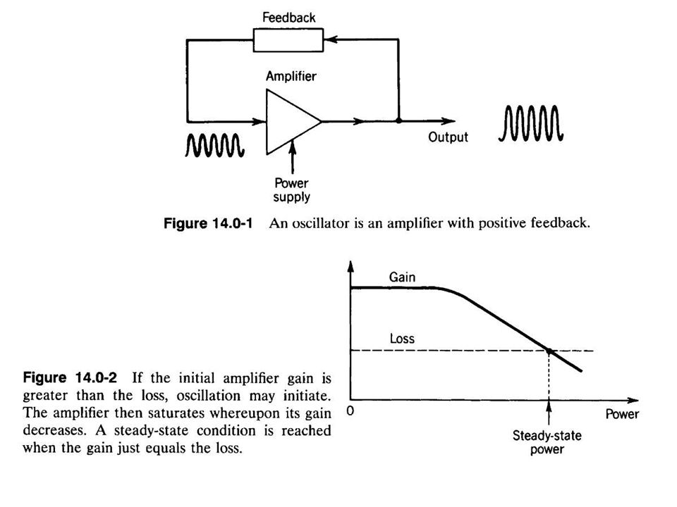
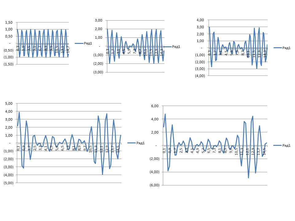
Oszcillátor – Wien osztóval
A Wien osztó saját frekvenciájánál (ω = 1/RC) a kimenő feszültség a bemenő feszültség 1/3-ad része, és nincs fáziseltolás. Más frekvencián a fázis eltolódik és az átvitel kisebb. Ha egy ME-nél Wien-osztóval pozitív visszacsatolást hozunk létre, és a negatív visszacsatolással pontosan 3-szoros erősítést állítunk be (l. ábra), akkor a kimeneten − elvileg − stabil amplitúdójú és frekvenciájú szinuszos feszültség lép fel.
 a kimenő feszültség a bemenő feszültség 1/3-ad része, és nincs fáziseltolás. Más frekvencián a fázis eltolódik és az átvitel kisebb. Ha egy ME-nél Wien-osztóval pozitív visszacsatolást hozunk létre, és a negatív visszacsatolással pontosan 3-szoros erősítést állítunk be (l. ábra), akkor a kimeneten − elvileg − stabil amplitúdójú és frekvenciájú szinuszos feszültség lép fel.")
8
Hullámhossz, frekvencia
532 nm – zöld fény c= 3 x 10⁸ m/s F= c/532 nm = 6 x 10¹⁴ Hz = GHz

9
Párhuzamosság Kilépő nyalábátmérő = 0,5 mm
5 m távolságban mekkora a fényfolt? 10 mm / 5 m = 10 mrad, a félszög, vagy divergencia 2 mrad 1 km távolságban?

10
Koherencia Mit jelent és hogyan mérjük?
Koherencia hossz – az a távolság, amelyen a fényhullám még interferencia képes, látható erősítés/kioltás mintázatot hoz létre

11
Teljesítmény Lézer pointer - 1 mW
Koncentrált fényfolt, látható hullámhosszon. Fénycső – 10 W Izzólámpa – 60 W

12
Gauss nyaláb - analitikus megoldása a hullámegyenletnek

13
Nyalábnyak, nyaláb divergencia és görbületi sugár

14
Nyalábátmérő és divergencia kapcsolata
lambda 6,33E-07 w mm theta (mrad) 0,00001 0,02 40,3 0,00003 0,06 13,4 0,00005 0,10 8,1 0,00007 0,14 5,8 0,00009 0,18 4,5 0,00011 0,22 3,7 0,00013 0,26 3,1 0,00015 0,30 2,7 0,00017 0,34 2,4 0,00019 0,38 2,1 0,00021 0,42 1,9 0,00023 0,46 1,8 0,00025 0,50 1,6 0,00027 0,54 1,5 0,00029 0,58 1,4 0,00031 0,62 1,3 0,00033 0,66 1,2
 0, ,02. 40,3. 0, ,06. 13,4. 0, ,10. 8,1. 0, ,14. 5,8. 0, ,18. 4,5. 0, ,22. 3,7. 0, ,26. 3,1. 0, ,30. 2,7. 0, ,34. 2,4. 0, ,38. 2,1. 0, ,42. 1,9. 0, ,46. 1,8. 0, ,50. 1,6. 0, ,54. 1,5. 0, ,58. 1,4. 0, ,62. 1,3. 0, ,66. 1,2.")
15
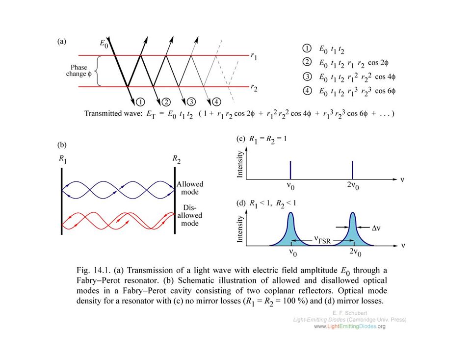
Fabry-Perot interferométer

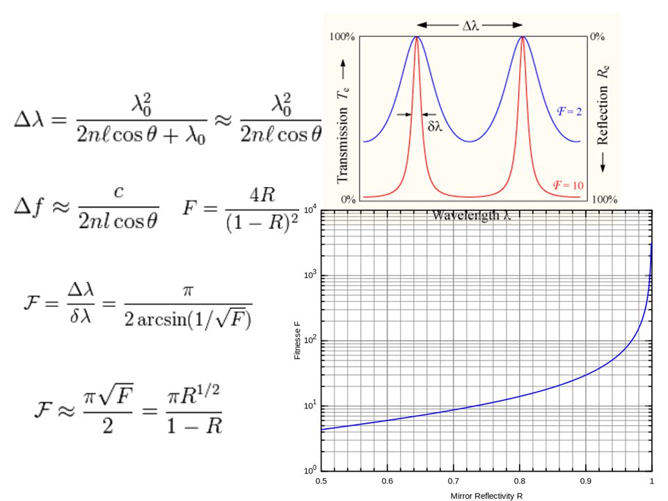
18
Frequency-dependent transmission of a linear Fabry–Pérot interferometer with mirror reflectivities of 80%. The finesse is ≈ 14, and perfect mode matching is assumed.

19
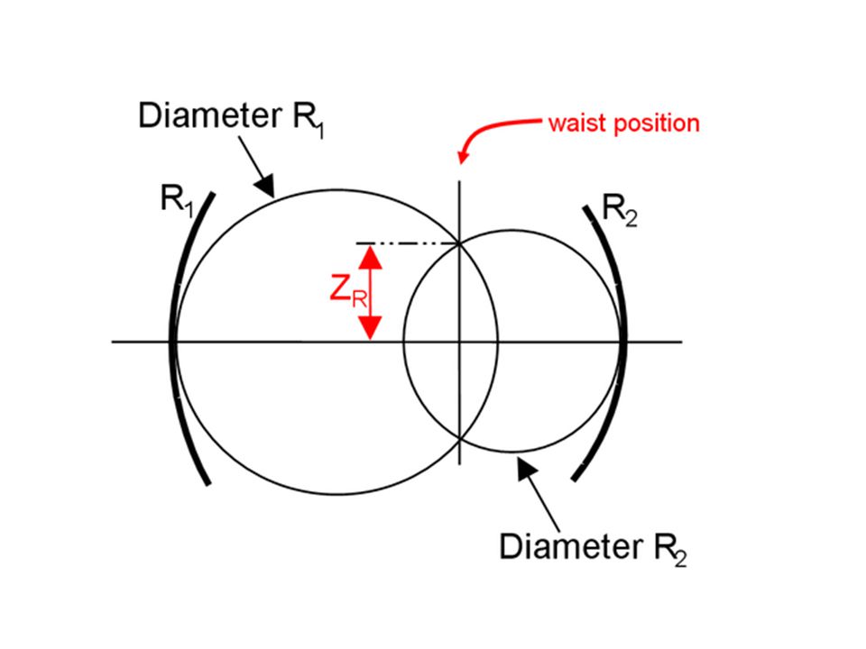
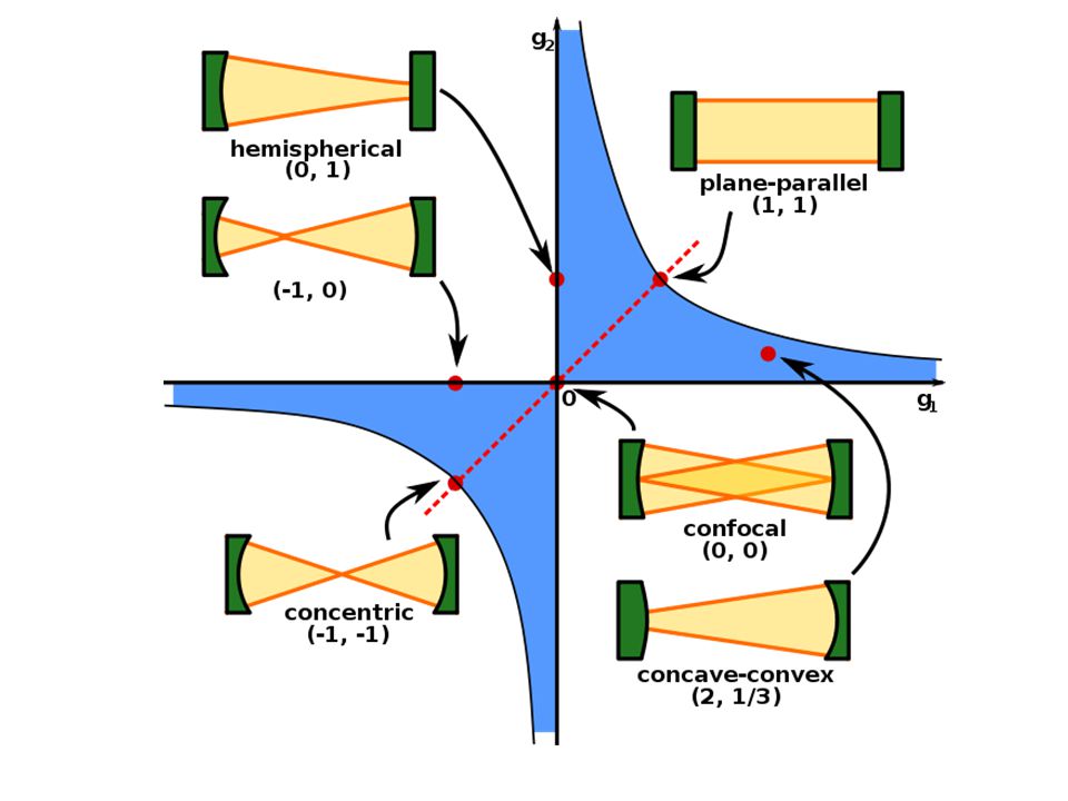
Optikai rezonátorok

22
Transzverzális rezonátor módusok

23
Optikai erősítők

24
This process is known as stimulated emission.
In a group of such atoms, if the number of atoms in the excited state is given by n2, the rate at which stimulated emission occurs is given by: where the proportionality constant B21 is known as the Einstein B coefficient for that particular transition, and ρ(ν) is the radiation density of the incident field at frequency ν. The rate of emission is thus proportional to the number of atoms in the excited state N2, and to the density of incident photons. At the same time, there will be a process of atomic absorption which removes energy from the field while raising electrons from the lower state to the upper state. Its rate is given by an essentially identical equation:
 is the radiation density of the incident field at frequency ν. The rate of emission is thus proportional to the number of atoms in the excited state N2, and to the density of incident photons. At the same time, there will be a process of atomic absorption which removes energy from the field while raising electrons from the lower state to the upper state. Its rate is given by an essentially identical equation:")
25
Spontaneous emission is the process by which an electron "spontaneously" (i.e. without any outside influence) decays from a higher energy level to a lower one. The process is described by the Einstein coefficient A21 (s−1) which gives the probability per unit time that an electron in state 2 with energy will decay spontaneously to state 1 with energy , emitting a photon with an energy E2 − E1 = hν.
 decays from a higher energy level to a lower one. The process is described by the Einstein coefficient A21 (s−1) which gives the probability per unit time that an electron in state 2 with energy will decay spontaneously to state 1 with energy , emitting a photon with an energy E2 − E1 = hν..")
26
Egyensúly esetén az alsó energia szintre
From the Maxwell–Boltzmann distribution we have for the number of excited atomic species i: where n is the total number density of the atomic species, excited and unexcited, k is Boltzmann's constant, T is the temperature, is the degeneracy (also called the multiplicity) of state i, and Z is the partition function.
 of state i, and Z is the partition function.")
27
From Planck's law of black-body radiation at temperature T we have for the spectral energy density at frequency ν

28
. Ha g1=g2, akkor Ha az alap és a gerjesztett állapot betöltöttsége egyenlő, az indukált emisszió és az abszorpció valószínűsége azonos!

29
Lézerek – félvezető lézerek, elektrolumineszcencia

30
. The lasing threshold is reached when the optical gain of the laser medium is exactly balanced by the sum of all the losses experienced by light in one round trip of the laser's optical cavity. This can be expressed, assuming steady-state operation, as

31
When LDs are under threshold current, they behave like a LED and the output light come from spontaneous emission. As the input current is increased and above threshold, the frequencies having a larger gain and smaller cavity loss begin to oscillate and the output spectrum changes significantly.

32
Each wavelength in the figure is called a longitudinal mode
Each wavelength in the figure is called a longitudinal mode. When the frequency spacing Δv between adjacent modes is far less than the frequency v itself, Δv can be calculated with the following equation. where n is the refractive index of the semiconductor material, l is the cavity length. For a typical design of n = 3.6, l = 250um, = 0.38, we get a Δv = 125 GHz. For wavelength λ = 850nm, the corresponding wavelength spacing is

33
Példa szilárdtestlézerre: Nd-YAG, fotolumineszcencia
Elterjedt lézertípus a Nd3+:YAG lézer. A Nd ionokat a YAG (Y3Al5O12 - ittrium-alumínium-gránát) kristályba (vagy esetleg üvegbe) építik, es ezen ionok két nívója közötti átmeneten működik a lézer. A hullámhossza: Nézet -> Élőfej és élőláb
 kristályba (vagy esetleg üvegbe) építik, es ezen ionok két nívója közötti átmeneten működik a lézer. A hullámhossza: Nézet -> Élőfej és élőláb.")
34
Tömbi szilárdtest-lézerek: pumpálás lézerdiódával
Nézet -> Élőfej és élőláb

35
Kérdések Hogyan működnek az optikai rezonátorok és mi a szerepük a lézerekben? Mi az optikai erősítés elve és feltétele? Hogyan néz ki egy LED és egy félvezetőlézer spektruma? Mi okozza a különbséget? Mi ez elektrolumineszcencia, a fotolumineszcencia, és szerepük a lézerek működésében?

36
Mode locking – psec/fsec lézerek

37
When LDs are under threshold current, they behave like a LED and the output light come from spontaneous emission. As the input current is increased and above threshold, the frequencies having a larger gain and smaller cavity loss begin to oscillate and the output spectrum changes significantly.

39
BME Atomfizika Tanszék

40
Nemlineáris optikai eszközök
A dielektromos polarizáció nemlineáris függvénye a térerősségnek Általában nagy térerősségek esetén figyelhető meg, pl. impulzusüzemű lézerek segítségével A szuperpozíció elve nem érvényes

41
Frekvencia kétszerezés - fázis illesztés

42
The non-linear mirror mode-locked (NLMML) laser
Schematic diagram of (actively Q-switched and) non-linear mirror mode-locked laser. OC { output coupler with 100% reflectivity at 532nm and 78% reflectivity at 1064 nm; RM { rear mirror: the pump surface of it is coated for anti-reflection at 808nm and the cavity surface is coated for 100%, reflectivity at 1064 nm; M1 and M2 { curved mirrors with radius of curvature, 500 and 250mm respectively and reflectivity of 100% at 1064 nm. AOQS { acousto-optic Q-switch. (LBO - Lithium triborate)
 non-linear mirror mode-locked laser. OC { output coupler with 100% reflectivity at 532nm and 78% reflectivity at 1064 nm; RM { rear mirror: the pump surface of it is coated for anti-reflection at 808nm and the cavity surface is coated for 100%, reflectivity at 1064 nm; M1 and M2 { curved mirrors with radius of curvature, 500 and 250mm respectively and reflectivity of 100% at 1064 nm. AOQS { acousto-optic Q-switch. (LBO - Lithium triborate)")
43
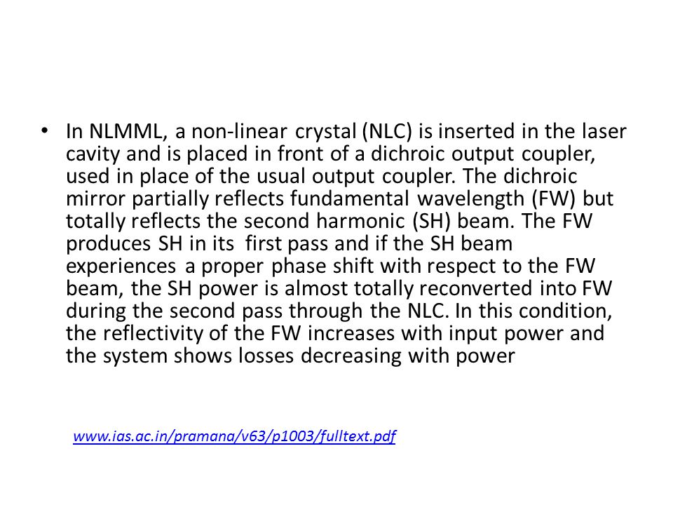
In NLMML, a non-linear crystal (NLC) is inserted in the laser cavity and is placed in front of a dichroic output coupler, used in place of the usual output coupler. The dichroic mirror partially reflects fundamental wavelength (FW) but totally reflects the second harmonic (SH) beam. The FW produces SH in its first pass and if the SH beam experiences a proper phase shift with respect to the FW beam, the SH power is almost totally reconverted into FW during the second pass through the NLC. In this condition, the reflectivity of the FW increases with input power and the system shows losses decreasing with power
45
Optikai Kerr effektus

46
Kerr-lens mode-locking
Alkalmazása elsősorban fsec lézerekben

48
Schematic of KLM Ti:Sapphire laser cavity
Schematic of KLM Ti:Sapphire laser cavity. Mirror M1 is a 10% output coupler. M2 and M3 have 10 cm radius of curvature. Two Brewster angle fused silica prisms (P1 and P2) are placed 62 cm apart for dispersion compensation.
 are placed 62 cm apart for dispersion compensation.")
49
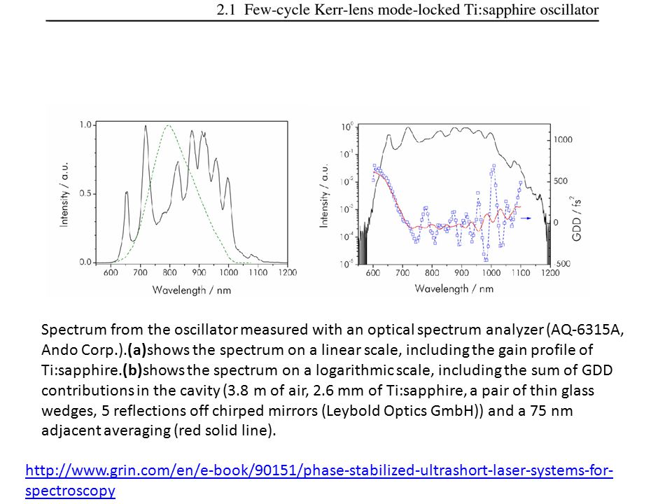
Spectrum from the oscillator measured with an optical spectrum analyzer (AQ-6315A, Ando Corp.).(a)shows the spectrum on a linear scale, including the gain profile of Ti:sapphire.(b)shows the spectrum on a logarithmic scale, including the sum of GDD contributions in the cavity (3.8 m of air, 2.6 mm of Ti:sapphire, a pair of thin glass wedges, 5 reflections off chirped mirrors (Leybold Optics GmbH)) and a 75 nm adjacent averaging (red solid line).
50
A typical oscillator spectrum is shown in figure together with the net cavity dispersion. Although the gain bandwidth of the Ti:sapphire crystal extends only from nm (at -10 dB below the maximum), the generated spectrum from the oscillator extends beyond this region. This means that most of the light at the wings of the spectrum is not generated through lasing but by self-phase modulation in the crystal, a phenomenon previously observed Self-phase modulation (SPM) is a nonlinear optical effect of light-matter interaction. An ultrashort pulse of light, when travelling in a medium, will induce a varying refractive index of the medium due to the optical Kerr effect. This variation in refractive index will produce a phase shift in the pulse, leading to a change of the pulse's frequency spectrum.
 is a nonlinear optical effect of light-matter interaction. An ultrashort pulse of light, when travelling in a medium, will induce a varying refractive index of the medium due to the optical Kerr effect. This variation in refractive index will produce a phase shift in the pulse, leading to a change of the pulse s frequency spectrum.")
51
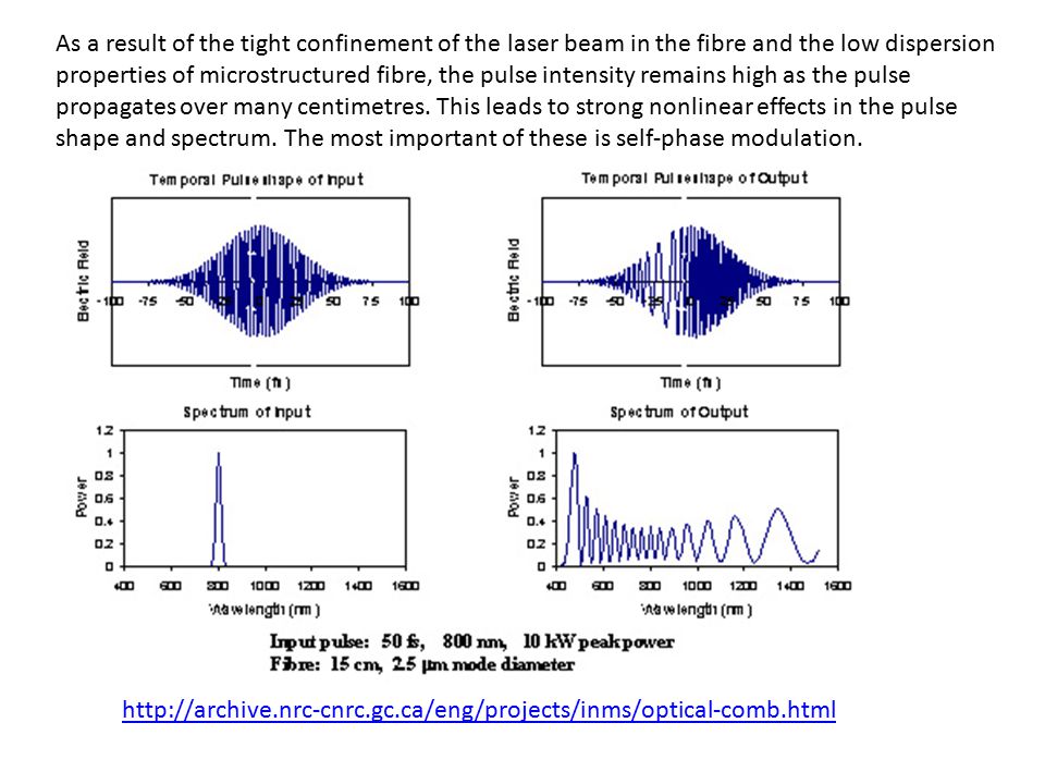
As a result of the tight confinement of the laser beam in the fibre and the low dispersion properties of microstructured fibre, the pulse intensity remains high as the pulse propagates over many centimetres. This leads to strong nonlinear effects in the pulse shape and spectrum. The most important of these is self-phase modulation.
52
Interferometric autocorrelation of the oscillator pulses, measured with an autocorrelator designed for femtosecond pulses (Femtometer, Femtolasers GmbH). The frequency-doubling crystal used is a 10-µm-thickβ-BaB2O4(BBO) crystal. The FWHM pulse duration is 6.2 fs. The dashed line shows the transform-limited pulse as derived from the spectrum in fig. 8 with a FWHM width of 4.7 fs.
 crystal. The FWHM pulse duration is 6.2 fs. The dashed line shows the transform-limited pulse as derived from the spectrum in fig. 8 with a FWHM width of 4.7 fs..")
53
10 fsec impulzus fizikai hossza 3 mikron!
Setup of an intensity autocorrelator. BS = beam splitter. Setup of an interferometric autocorrelator. BS = beam splitter.

54
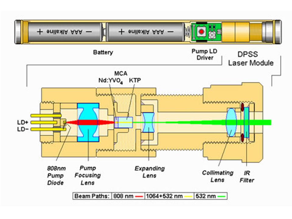
Advanced Diode-Pumped Solid-State (DPSS) Lasers.
From UV to IR and from CW to fs: Modelocked DPSSL (100 fs ps) Q-Switched DPSSL (Actively & Passively Q-Switched, Microchip, <1 ns, >1 mJ) CW DPSSL (Single Frequency, 532 nm, 1064 nm) Available Wavelengths for Our DPSS Lasers: Nd:YAG 946 nm, 473 nm, 315 nm, 236 nm 1064 nm, 532 nm, 355 nm, 266 nm 1319 nm, 660 nm, 440 nm, 330 nm Nd:YVO4 914 nm, 457 nm, 305 nm, 228 nm 1342 nm, 671 nm, 447 nm, 336 nm Nd:YLF 1047 nm, 523 nm, 349 nm, 262 nm 1053 nm, 527 nm, 351 nm, 263 nm Yb:YAG 1030 nm, 515 nm, 343 nm, 257 nm
 Q-Switched DPSSL (Actively & Passively Q-Switched, Microchip, <1 ns, >1 mJ) CW DPSSL (Single Frequency, 532 nm, 1064 nm) Available Wavelengths for Our DPSS Lasers: Nd:YAG. 946 nm, 473 nm, 315 nm, 236 nm nm, 532 nm, 355 nm, 266 nm nm, 660 nm, 440 nm, 330 nm. Nd:YVO nm, 457 nm, 305 nm, 228 nm nm, 671 nm, 447 nm, 336 nm. Nd:YLF nm, 523 nm, 349 nm, 262 nm nm, 527 nm, 351 nm, 263 nm. Yb:YAG nm, 515 nm, 343 nm, 257 nm. gclid=CM7U_rXGpbMCFUFb3god7GoAQg.")
Hasonló előadás


 -- sàvszűrő ~àllandó Q-val ? inhibició, komodulalt takaras leengedese (CMR) -- mindez.>")


Auto-indexing enabled b)Auto-indexing disabled c)Nem eldönthető 1.>")


 Lézerspektroszkópia Kubinyi Miklós (kubinyi@mail.bme.hu, 438-1120)>")


 of polymers, monomers, plasticizers, lubricants, antidegradantes (antioxidantes,>")
 Az NO PIE görbéje.>")

