Előadást letölteni
Az előadás letöltése folymat van. Kérjük, várjon

1
Felületmódosítás Korszerű anyagok és technológiák, MSc 2015

2
A felületi tulajdonságok tudománya: átfogó (interdiszciplináris) terület A felület a tiszta fizikai és kémiai tulajdonságok szemszögéből. Topográfiával kapcsolatos tulajdonságok (felületi érdesség). Tágabb értelemben: „surface engineering”: komplex nézőpont Kapcsolat a felületi tulajdonságok, az alkalmazás és az alkalmazott technológiák között. (Tiszta fizikai és kémiai tulajdonságok: alapkutatás szemszöge.) A felületek tulajdonsága a felhasználók szempontjából: „surface engineering”.
. Tágabb értelemben: „surface engineering : komplex nézőpont Kapcsolat a felületi tulajdonságok, az alkalmazás és az alkalmazott technológiák között. (Tiszta fizikai és kémiai tulajdonságok: alapkutatás szemszöge.) A felületek tulajdonsága a felhasználók szempontjából: „surface engineering ..")
3
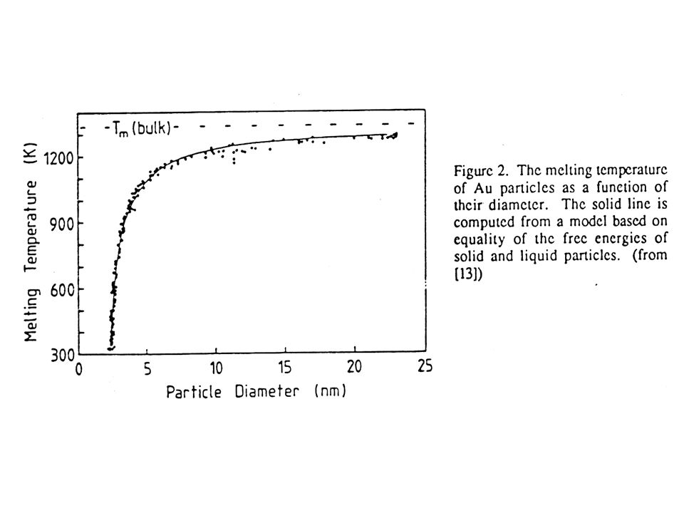
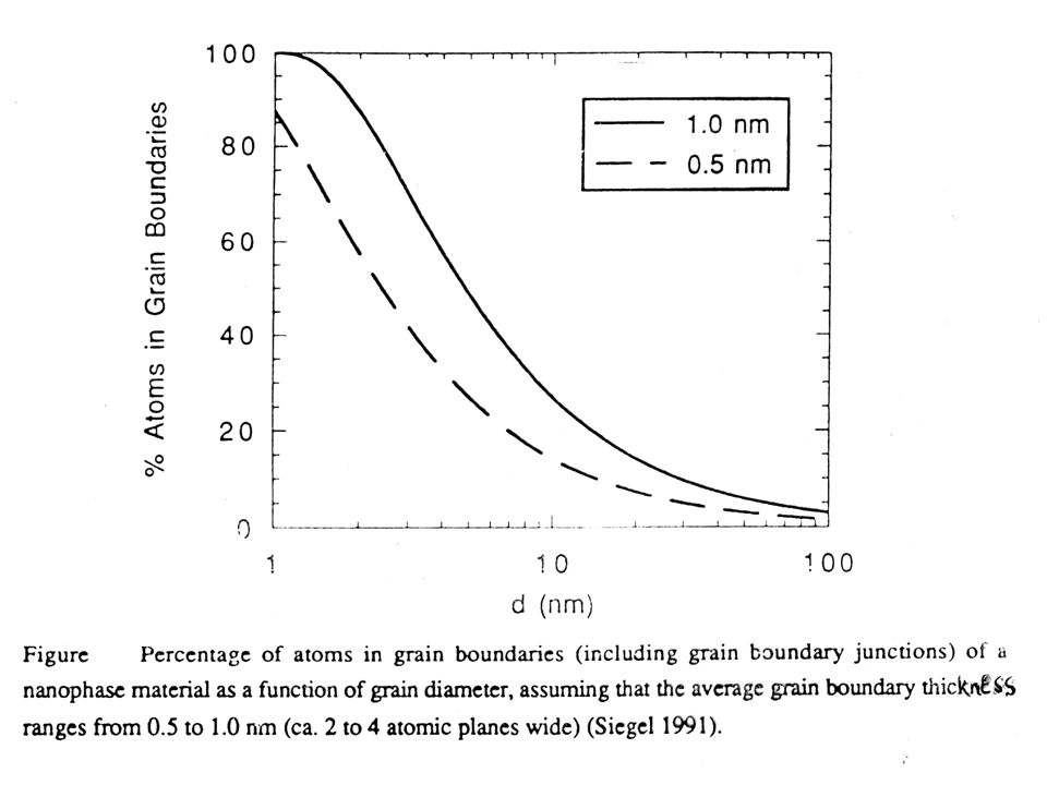
Kondenzált anyagok nagy fajlagos felülettel: a „komplexitás” alapja a felület Felületi tulajdonságok kialakulása ← klaszterek tulajdonsága (mérethatás): „Méretfüggő” tulajdonságok: átmenet az önálló atomtulajdonságok és a termodinamikailag stabil makroszkópos tulajdonságok között; A redukált ionizációs energia különböző szabadfelületű fémklaszterek esetében a klaszterátmérő reciprokának függvényében
: „Méretfüggő tulajdonságok: átmenet az önálló atomtulajdonságok és a termodinamikailag stabil makroszkópos tulajdonságok között; A redukált ionizációs energia különböző szabadfelületű fémklaszterek esetében a klaszterátmérő reciprokának függvényében")
6
Aim: the local modification of surface properties changing either the local composition or the structure or both of them. The desired surface properties are often contradict to those in the bulk! (i.e. local hardness, local corrosion resistance) examples: development of peculiar compositional relations on the surface of semiconductors The development of hard, wear- or corrosion-resistant surfaces on cutting, drilling tools Development of optical or decorative layers Two alternatives: Covering the surface with protective layer (corrosion resistant layers) Structural or compositional changes in the surface layer
 examples: development of peculiar compositional relations on the surface of semiconductors The development of hard, wear- or corrosion-resistant surfaces on cutting, drilling tools Development of optical or decorative layers Two alternatives: Covering the surface with protective layer (corrosion resistant layers) Structural or compositional changes in the surface layer.")
7
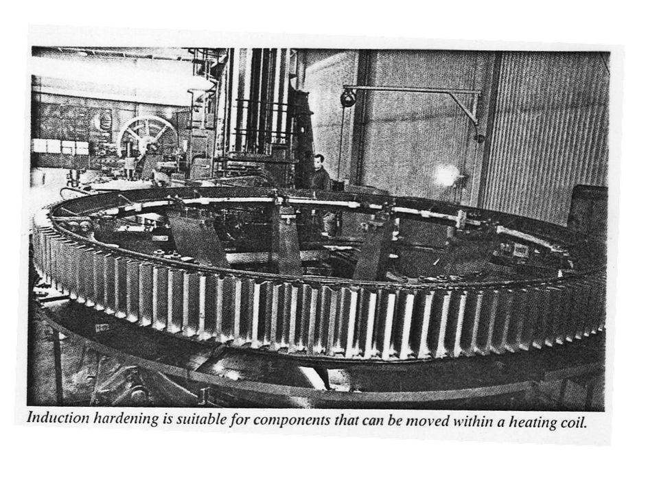
Traditional methods Increase of non-metallic element concentration in the surface layer, using heterogeneous reaction. i.e. iron/steel heating in appropriate gas-mixture (carbonization, decarbonization, nitridation) CH 4 [C]Fe + 2H 2 CH 4 /H 2 2NH 3 [N]Fe + 3H 2 NH 3 /H 2 Layer deposition using electrochemical or chemical methods Hard chromium-layer (3-500 μm, HV 900-1100) Ni-P amorphous layer (3-30 μm, HV 1300) Surface hardening using inductive heating and subsequent rapid cooling Inductor Cog wheel Inductor Cog wheel
 CH 4 [C]Fe + 2H 2 CH 4 /H 2 2NH 3 [N]Fe + 3H 2 NH 3 /H 2 Layer deposition using electrochemical or chemical methods Hard chromium-layer (3-500 μm, HV ) Ni-P amorphous layer (3-30 μm, HV 1300) Surface hardening using inductive heating and subsequent rapid cooling Inductor Cog wheel Inductor Cog wheel.")
9
forrás: Szurdán Szabolcs

11
x Példa: Al-Si bevonat „press hardening” technológiához ausztenitesítés: 880-950°C - ~ 10 % Si

12
Deposition of thin layers by physical methods (Physical Vapour Deposition, PVD) favour: High melting point metals can be deposited to low substrat temperature because T substrat can be low The electrical conductivity of substrate not necessary Complex multilayers can be deposited Alloy deposition is also possible „clean technology” (without the formation of products causing environmental pollution) limits: Expensive (vacuum circumstances)
 favour: High melting point metals can be deposited to low substrat temperature because T substrat can be low The electrical conductivity of substrate not necessary Complex multilayers can be deposited Alloy deposition is also possible „clean technology (without the formation of products causing environmental pollution) limits: Expensive (vacuum circumstances)")
13
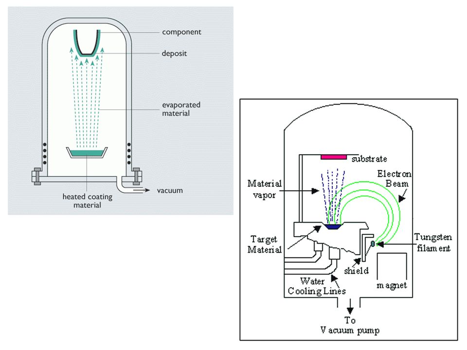
PVD (physical vapor deposition) T he original, traditional technologies: chemical reactions are not included ( i.e. mirror production) Schematic illustration of the principle The technical arrangement Crucial in every deposition is the layer duration, which is influenced mainly by the surface preparation (cleaning) Heating Substrate Source Vacuum system Source Chamber Window Layer thickness measure Substrate holder Evaporate source Cover plate Freezer Diffusion pump Pre-vacuum pumps Valve Mask
 Schematic illustration of the principle The technical arrangement Crucial in every deposition is the layer duration, which is influenced mainly by the surface preparation (cleaning) Heating Substrate Source Vacuum system Source Chamber Window Layer thickness measure Substrate holder Evaporate source Cover plate Freezer Diffusion pump Pre-vacuum pumps Valve Mask.")
14
Physical Vapour Deposition Source: Platit

16
The real structure of the deposited layer versus the substrat to melting point temperature Deposition of TiN layer on the surface of tools for the purpose of surface hardenening

17
The dimensions Source: Platit

18
Some another exmples Source: Platit

19
The machined length versus the main machining parameters: cutting speed (a) and feed (b) ( TiN coated, o TiN coated and newly grinded, □nitride coating ■ without coating Machined length [m] Cutting speed [m/min] Feed [mm/rev]
![The machined length versus the main machining parameters: cutting speed (a) and feed (b) ( TiN coated, o TiN coated and newly grinded, □nitride coating ■ without coating Machined length [m] Cutting speed [m/min] Feed [mm/rev]](http://images.slideplayer.hu/37/10722112/slides/slide_19.jpg "The machined length versus the main machining parameters: cutting speed (a) and feed (b) ( TiN coated, o TiN coated and newly grinded, □nitride coating ■ without coating Machined length [m] Cutting speed [m/min] Feed [mm/rev]")
20
Chemical Vapour Deposition, (CVD) basic principles In the original form, the procedure consist of two isothermal reactions: a.)at T1 temperature M +nX MX n (M layer forming metal, X halogen) At T1 a volatile compound is formed b.) at T2 (T2 > T1 ) MX n M + nX Thermal decomposition of MXn occur on the substrate surface Subsequently the decomposition process, the halogen molecule is circuated (in order to form new volatile molecules) Typical chemical reactions in the CVD procedure: Metal-halogenides are often used as precursor materials in these techniques. The reason: volatile compounds (high tension even at low temperatures!) (see tables) Besides the metal-layer depositions, the method also used for compound depositions (refractory carbides, silicides, borides)
 (see tables) Besides the metal-layer depositions, the method also used for compound depositions (refractory carbides, silicides, borides).")
21
Typical CVD reactions CrI 2 (g) 800-1000 ºC Cr(s) + 2I(g) WF 6 (g) + 3H 2 (g) 350-1000ºC W(s) + 6HF(g) WCl 6 (g) + 3H 2 (g) 500-1100ºC W(s) + 6HCl(g) TaCl 5 (g) + 5 / 2 H 2 (g) 700-1100ºC Ta(s) + 5HCl(g) (C 8 H 10 ) 2 Cr(g) 400-600ºC a Cr(s) + 2C 8 H 10 (g) Ni(CO) 4 150-200ºC b Ni(s) + 4CO (g) Al 2 Cl 6 (g) + 3H 2 O (g) 800-1400ºC Al 2 O 3 (s) + 6HCl(g) BCl 3 (g) + NH 3 (g) 500-1500ºC BN(s) + 3HCl(g) TiCl 4 (g) + CH 4 (g) 800-1100ºC TiC(s)+ 4HCl(g) Ga(g) + AsCl 3 (g) + 3 / 2 H 2 (g) 750-900ºC GaAs(s) + 3HCl(g) Typical reactants, processing parameters for a few depositions
 ºC Cr(s) + 2I(g) WF 6 (g) + 3H 2 (g) ºC W(s) + 6HF(g) WCl 6 (g) + 3H 2 (g) ºC W(s) + 6HCl(g) TaCl 5 (g) + 5 / 2 H 2 (g) ºC Ta(s) + 5HCl(g) (C 8 H 10 ) 2 Cr(g) ºC a Cr(s) + 2C 8 H 10 (g) Ni(CO) ºC b Ni(s) + 4CO (g) Al 2 Cl 6 (g) + 3H 2 O (g) ºC Al 2 O 3 (s) + 6HCl(g) BCl 3 (g) + NH 3 (g) ºC BN(s) + 3HCl(g) TiCl 4 (g) + CH 4 (g) ºC TiC(s)+ 4HCl(g) Ga(g) + AsCl 3 (g) + 3 / 2 H 2 (g) ºC GaAs(s) + 3HCl(g) Typical reactants, processing parameters for a few depositions")
22
layer reactant Add. reactant T ( C) pressure (kPa) Deposition velocity (nm/min) WWF 6 WCl 6 W(CO) 6 H 2 --- 250-1200 850-1400 1400-2000 180-600 0,133-100 0,133-2,67 0,013- 0,133 0,127-50,8 0,254-38,1 2,54-50,8 0,127-1,27 MoMoF 6 MoCl 5 Mo(CO) 6 H 2 --- 700-1200 650-1200 1250-1600 150-600 2,67-46,7 0,133-2,67 1,33-267 0,013- 0,133 1,27-30,5 1,27-20,3 2,54-17,8 0,127-1,27 ReReF 6 ReCl 5 NbCl 5 NbBr 5 H 2 --- H 2 --- H 2 400-1400 800-1200 1880 800-1200 0,133-13,3 0,133-26,7 0,133-100 0,133-2,67 0,133-100 1,27-15,2 0,076-25,4 2,54 0,076-25,4 NbNbCl 5 NbBr 5 H 2 --- H 2 800-1200 1880 800-1200 0,133-100 0,133-2,67 0,133-100 0,076-25,4 2,54 0,076-25,4 TaTaCl 5 H 2 --- 800-1200 2000 0,133-100 0,133-2,67 0,076-25,4 2,54 ZrZrI 4 ---1200-16000,133-2,671,27-2,54 HfHfI 4 ---1400-20000,133-2,671,27-2,54 NiNi(CO) 4 ---150-25013,3-1002,54-38,1 FeFe(CO) 5 ---150-45013,3-1002,54-50,8 VVI 2 ---1000-12000,133-2,671,27-2,54 CrCrI 3 ---1000-12000,133-2,671,27-2,54 TiTiI 4 ---1000-14000,133-2,671,27-2,54
 pressure (kPa) Deposition velocity (nm/min) WWF 6 WCl 6 W(CO) 6 H , ,133-2,67 0,013- 0,133 0,127-50,8 0,254-38,1 2,54-50,8 0,127-1,27 MoMoF 6 MoCl 5 Mo(CO) 6 H ,67-46,7 0,133-2,67 1, ,013- 0,133 1,27-30,5 1,27-20,3 2,54-17,8 0,127-1,27 ReReF 6 ReCl 5 NbCl 5 NbBr 5 H H H ,133-13,3 0,133-26,7 0, ,133-2,67 0, ,27-15,2 0,076-25,4 2,54 0,076-25,4 NbNbCl 5 NbBr 5 H H , ,133-2,67 0, ,076-25,4 2,54 0,076-25,4 TaTaCl 5 H , ,133-2,67 0,076-25,4 2,54 ZrZrI ,133-2,671,27-2,54 HfHfI ,133-2,671,27-2,54 NiNi(CO) ,3-1002,54-38,1 FeFe(CO) ,3-1002,54-50,8 VVI ,133-2,671,27-2,54 CrCrI ,133-2,671,27-2,54 TiTiI ,133-2,671,27-2,54.")
23
The important metals and ceramics produced by the CVD method MetalsCu, Be, Al, Ti, Zr, Hf, Th, Ge, Sn, Pb, V, Nb, Ta, As, Sb, Bi, Cr, Mo, W, U, Re, Fe, Co, Ni, Ru, Rh, Os, Ir, Pt Graphite carbides karbonC, B 4 C, SiC, TiC, ZrC, HfC, ThC, ThC 2,VC, NbC, Nb 2 C, TaC, Ta 2 C, CrC, Cr 4 C, Cr 7 C 3, Cr 3 C 2, MoC, Mo 2 C, WC, W 2 C, VC 2, V 2 C 3 NitridesBN, TiN, ZrN, VN, NbN, TaN, Si 3 N 4 Boron and boridesB, AlB 2, TiB 2, ZrB 2, ThB 4, ThB, NbB, TaB, MoB, Mo 3 B 2, WB, Fr 2 B, FeB, NiB, Ni 3 B 2, Ni 2 B Silicon and silicidesSi és Ti, Zr, Nb, Mo, W, Mn, Fe, Ni, Co and varies silicides OxidesAl 2 O 3, BeO, SiO 2, ZrO 2, Cr 2 O 3, SnO 2

24
Examples for the compound-layer deposition The TiN layer deposition: 2 TiCl 4 +4 H 2 +N 2 2 TiN +8HCl Al 2 O 3 layer deposition: 2AlCl 3 +3CO 2 +H2 Al 2 O 3 +3CO +6HCl

25
The scheme of complete unit for CVD technology Gases Halide preparatory Gas mixer Programming unit Deposition chambers Outgoing gas cleaner and neutralizer Heating bell Vacuum pump Heating controller Heating bell Gas supply

26
The properties of deposits produced by CVD, layer-substrate: the compatibility

27
Favour: -high temperature: deposit accomodat even the complicated, irregular surfaces (inner surfaces can be covered)
")
28
Another example Tantállal bevont gégecső

29
The limits: The high substrat temperature (for example for structural or carbon steels is not recommended! 6-800 o C!) Expensive reactants
 Expensive reactants.")
30
The properties of CVD-produced policrystalline diamond layers: high chemical resistance, high hardness, high wear resistance, low frictional resistance Polymer Diamond DLC Graphite Gyémánt és gyémántszerű amorf rétegek DLC: Diamond-Like Carbon

31
Hardness and young moduli of carbon- based coated layers Me: fém az elektromos vezetőképesség növeléséhez, fém- karbidok H: hidrogéntartalom a C 2 H 2 elbomlásából a: amorf fázis tartalmú réteg Si: szilíciumtartalom i-C: mátrix sp 3 -as kötésekkel, de amorf

32
The techniques of plasma spraying Helium Hővezetési tényező Plazmagáz energiatartalma

33
Shematic drawing of plasma spraying and the SEM photograph of the sprayed coating

34
Characteristics of plasma-sprayed layers Improvement of Succesfully applied for Abrasive properties Hardness Corrosion resistance (Especially in those cases, when the base material is low-cost improvement of bio-compatibility (implanted parts) the surface improvement of carbon- steels surface hardness increase corrosion resistance increase
 the surface improvement of carbon- steels surface hardness increase corrosion resistance increase")
35
The modes of plasma welding: inner, outher wire supply, powder supply

36
The laser surface treatments

37
The effectivity highly depends on the absorption degree The absorption degree of various laser beams as a function of wavelengths Excimer laser Iron Wavelength ( m) Absorption degree [%] Nd::YaG laser Diode laser Excimer laser CO 2 laser
![The effectivity highly depends on the absorption degree The absorption degree of various laser beams as a function of wavelengths Excimer laser Iron Wavelength ( m) Absorption degree [%] Nd::YaG laser Diode laser Excimer laser CO 2 laser](http://images.slideplayer.hu/37/10722112/slides/slide_37.jpg "The effectivity highly depends on the absorption degree The absorption degree of various laser beams as a function of wavelengths Excimer laser Iron Wavelength ( m) Absorption degree [%] Nd::YaG laser Diode laser Excimer laser CO 2 laser")
38
The thickness of hardened layer as a function scanning rate on steels with various surface roughness The absorption degree also depends on the surface roughness Milled surface Grinded surface Polished surface Material: CMo4 Feed [mm/min] Hardened layer thicjness [mm]
![The thickness of hardened layer as a function scanning rate on steels with various surface roughness The absorption degree also depends on the surface roughness Milled surface Grinded surface Polished surface Material: CMo4 Feed [mm/min] Hardened layer thicjness [mm]](http://images.slideplayer.hu/37/10722112/slides/slide_38.jpg "The thickness of hardened layer as a function scanning rate on steels with various surface roughness The absorption degree also depends on the surface roughness Milled surface Grinded surface Polished surface Material: CMo4 Feed [mm/min] Hardened layer thicjness [mm]")
39
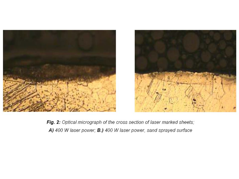
Laser marking on steel surfaces

40
The local structural change as the basis of code formation Depending on the applied energy density various structural changes can be induced (phase transformation, recrystallisation etc)
")
Hasonló előadás


Auto-indexing enabled b)Auto-indexing disabled c)Nem eldönthető 1.>")


 Mizsei János 2013.>")
 Habilitációs előadás dr. Mizsei János, 2003.>")

